SE440BX Motherboard Product Guide Order Number: 697967-001
Revision History Revision Revision History Date -001 First release of the SE440BX Motherboard Product Guide. February, 1998 If an FCC declaration of conformity marking is present on the board, the following statement applies: FCC Declaration of Conformity This device complies with Part 15 of the FCC Rules.
Contents 1 Motherboard Features Features Summary............................................................................................................... 7 Components......................................................................................................................... 8 Back Panel I/O Connectors .................................................................................................. 9 Microprocessor...........................................................................
Contents How to Install Memory.........................................................................................................27 How to Remove Memory.....................................................................................................29 How to Replace the Battery.................................................................................................30 How to Clear the Passwords ...............................................................................................
SE440BX Motherboard Product Guide A Error Messages BIOS Beep Codes ...............................................................................................................57 BIOS Error Messages .........................................................................................................57 B Regulatory and Integration Information Regulatory Compliance .......................................................................................................59 Product Certification Markings .
Contents 14. 15. 16. 17. 18. 19. 20. 21. 22. 23. 24. 25. 26. 27. 28. 29. 30. 31. 32. 33. 34. 35. 36. 37. 38. 39. 40. 41. vi Security Menu ............................................................................................................41 Power Menu ...............................................................................................................42 Boot Menu ..................................................................................................................
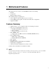
1 Motherboard Features This chapter gives an overview of the SE440BX motherboard, including: • Features • Components • Back panel I/O connectors The remaining chapters explain how to: • Add or upgrade components like processors or memory • Use the BIOS Setup program to modify the motherboard’s configuration • Upgrade the BIOS Features Summary • • • • • • • • • ATX form factor of 12 x 7.
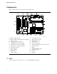
Motherboard Features Components Figure 1 shows the major components on the motherboard.
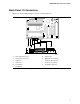
SE440BX Motherboard Product Guide Back Panel I/O Connectors Figure 2 shows the back panel I/O connectors on the motherboard. A B F C D H E G I J K OM06985 A PS/2† B C keyboard or mouse G Serial Port B PS/2 keyboard or mouse H MIDI/game Port (optional) USB Port 1 I Audio Line Out (optional) D USB Port 0 J Audio Line In (optional) E Serial Port A K Audio Mic In (optional) F Parallel Port Figure 2.
Motherboard Features Microprocessor The motherboard supports a single Pentium II processor operating at any of the Pentium II processor speeds, voltages, and bus frequencies. Processors are not included with the SE440BX motherboard and must be purchased separately. The processor is packaged in a Single Edge Contact (S.E.C.) cartridge. The cartridge includes the processor core, second-level cache subsystem, thermal plate, and back cover.
SE440BX Motherboard Product Guide Input/Output (I/O) Controller The I/O controller handles the exchange of information between the processor and external devices like the mouse and keyboard or a printer that are connected to the computer.
Motherboard Features • • ✏ Support for up to 127 physical devices Guaranteed bandwidth and low latencies appropriate for telephony, audio, and other applications NOTE Computer systems that have an unshielded cable attached to a USB port may not meet FCC Class B requirements, even if no device or a low-speed USB device is attached to the cable. Use a shielded cable that meets the requirements for a high-speed USB device. A.G.P. The A.G.P.
SE440BX Motherboard Product Guide IDE Auto Configuration If you install an IDE device (e.g., a hard drive) in your computer, the IDE auto-configuration utility in the BIOS automatically detects and configures the device for your computer. You do not need to run the BIOS Setup program after installing an IDE device.
Motherboard Features Power Management The motherboard supports two types of power management — Advanced Power Management (APM) and Advanced Configuration and Power Interface (ACPI).
SE440BX Motherboard Product Guide Wake on Ring Wake on Ring enables the computer to wake from sleep or soft-off mode when a call is received on a telephony device, such as a modem, configured for operation on COM1. The first incoming call powers up the computer. A second call must be made to access the computer. To access this feature use the Wake on Ring connector. See Chapter 5 for the location and pinouts of the Wake on Ring connector.
Motherboard Features Crystal Semiconductor CS4236B Audio Codec The CS4236B audio codec’s features include: • Compatibility with Sound Blaster†, Sound Blaster Pro†, and Windows Sound System • MPU-401 compatible MIDI and joystick interfaces • Advanced MPC3-compliant input and output mixer Crystal Semiconductor CS4611 PCI Audio Accelerator The CS4611’s PCI bus interface enables burst mode transfers of audio data between the system bus and the device’s internal DMA engine and stream processor.
2 Installing and Replacing Motherboard Components This chapter describes the following: • How to install and remove the motherboard • How to install a processor • How to prepare the motherboard for a boxed Pentium II processor • How to install and remove memory • How to replace the battery • How to use the configuration jumper to set processor speed and clear passwords Before You Begin CAUTION Before you install this motherboard in a chassis, see Appendix B for regulatory requirements and precautions.
Installing and Replacing Motherboard Components How to Install and Remove the Motherboard Refer to your chassis manual for instructions on installing and removing the motherboard. The motherboard is secured to the chassis by seven screws. Figure 3 shows the locations of the mounting screw holes. ✏ NOTES You will need a Phillips (#2 bit) screwdriver. Refer to Appendix B for regulatory requirements and installation instructions and precautions.
SE440BX Motherboard Product Guide Install the Retention Mechanism To install the retention mechanism, follow these steps: 1. Observe the precautions in “Before You Begin” (see page 17). 2. Find the Slot 1 connector on the motherboard (see Figure 4). C A B D OM07025 A Retention bracket C Fastener retainer pins B Press-fit fasteners D Slot 1 connector Figure 4. Installing the Processor Retention Mechanism 3.
Installing and Replacing Motherboard Components Install the Processor To install the processor, follow these steps: 1. Insert the processor in the retention mechanism as shown in Figure 5. 2. Press down on the processor until it is firmly seated in the Slot 1 connector and the latches on the processor lock into place. B B A OM07061 A Retention mechanism B Latches Figure 5.
SE440BX Motherboard Product Guide 3. Slide the top heatsink support bar onto the retaining pins of the support’s base as shown in Figure 6. A B OM07060 A Heatsink support bar B Retaining pins Figure 6. Installing the Heatsink Support Top Bar How to Set the Processor Speed Set the processor speed after you have installed or upgraded the processor. This procedure assumes that the motherboard is installed in the computer and the configuration jumper block is set to normal mode.
Installing and Replacing Motherboard Components CAUTION To avoid bending or breaking pins, use caution when removing or installing a jumper. To set the processor speed, follow these steps: 1. Observe the precautions in “Before You Begin” (see page 17). 2. Turn off all peripheral devices connected to the computer. Turn off the computer. 3. Remove the computer cover. 4. Find the configuration jumper block (see Figure 7). 5. Place the jumper on pins 2-3 as shown below. J8A1 1 3 OM07071 6.
SE440BX Motherboard Product Guide How to Upgrade to a Boxed Pentium® II Processor Use the instructions in this section to prepare the motherboard for a boxed Pentium II processor upgrade. To prepare for a boxed Pentium II processor upgrade, in brief you must: 1. Remove the heatsink support top bar and the installed processor. 2. Remove the heatsink support base. 3. Upgrade the processor. Detailed instructions follow for each of these procedures.
Installing and Replacing Motherboard Components 6. Remove the top bar of the heatsink support from the base as shown in Figure 8. Press in on the latches to release the top bar. B B A OM07059 A Heatsink support top bar B Latches Figure 8. Removing the Heatsink Support Top Bar and the Processor CAUTION Pressing on the motherboard or components while removing the processor can cause damage.
SE440BX Motherboard Product Guide Remove the Heatsink Support Base ✏ NOTE To remove the heatsink support base from the motherboard, you need a special removal tool (MID #58982) that is available from Dexter Design (call 503-648-7000 for ordering information). To remove the heatsink support base, follow these steps: 1. With your fingers, remove the two retention pins from the heatsink support base as shown in Figure 9. A B A OM07024 A Retention pins B Heatsink support base Figure 9.
Installing and Replacing Motherboard Components 2. Place the heatsink support removal tool over the two outside posts of the heatsink support base as shown in Figure 10. Make sure the tool completely engages the posts. A B OM07058 A Heatsink support removal tool B Heatsink support base Figure 10. Placing the Heatsink Support Base Removal Tool on the Retention Pins 3.
SE440BX Motherboard Product Guide Upgrade the Processor See the documentation that came with the boxed Intel Pentium II processor. How to Install Memory You can install from 8 MB to 384 MB of memory in the motherboard DIMM sockets. The board has DIMM sockets arranged as banks 0, 1, and 2. The motherboard supports the following memory features: • 168-pin DIMMs with gold-plated contacts • 66 or 100 MHz SDRAM • Non-ECC (64-bit) and ECC (72-bit) memory • 3.
Installing and Replacing Motherboard Components Figure 12 shows the location of the DIMM sockets. 0 1 2 OM07067 Figure 12. Location of DIMM Sockets To install DIMMs, follow these steps: 1. Observe the precautions in “Before You Begin” (see page 17). 2. Turn off all peripheral devices connected to the computer. Turn off the computer. 3. Remove the computer cover and locate the DIMM sockets. 4. Holding the DIMM by the edges, remove it from its antistatic package. 5.
SE440BX Motherboard Product Guide OM07068 Figure 13. Installing a DIMM How to Remove Memory To remove a DIMM, follow these steps: 1. Observe the precautions in "Before You Begin" (see page 17). 2. Turn off all peripheral devices connected to the computer. Turn off the computer. 3. Remove the computer cover. 4. Gently spread the retaining clips at each end of the socket. The DIMM pops out of the socket. 5. Hold the DIMM by the edges, lift it away from the socket, and store it in an antistatic package. 6.
Installing and Replacing Motherboard Components How to Replace the Battery When your computer is turned off, a lithium battery maintains the current time-of-day clock and the values in CMOS RAM current. Figure 14 shows the location of the battery. The battery should last about seven years. When the battery begins to die, it loses voltage; when the voltage drops below a certain level, the Setup program settings stored in CMOS RAM (for example, the date and time) might not be accurate.
SE440BX Motherboard Product Guide To replace the battery, follow these steps: 1. Observe the precautions in “Before You Begin” (see page 17). 2. Turn off all peripheral devices connected to the computer. Turn off the computer. 3. Remove the computer cover. 4. Locate the battery on the motherboard (see Figure 14). 5. With a medium flat-bladed screwdriver, gently pry the battery free from its socket. Note the orientation of the “+” and “-” on the battery. 6.
Installing and Replacing Motherboard Components How to Clear the Passwords This procedure assumes that the motherboard is installed in the computer and the configuration jumper block is set to normal mode. 1. 2. 3. 4. 5. Observe the precautions in “Before You Begin” (see page 17). Turn off all peripheral devices connected to the computer. Turn off the computer. Remove the computer cover. Find the configuration jumper block (see Figure 7). Place the jumper on pins 2-3 as shown below. J8A1 1 3 OM07071 6.
3 Using the Setup Program This chapter provides an overview of the Setup program. You can use the Setup program to change the configuration information and boot sequence for the computer. ✏ NOTE For reference purposes, you should write down the current Setup settings. When you make changes to the settings, update this record.
Using the Setup Program Setup Menus To enter the Setup program, turn the computer on and press when you see the message: Press Key if you want to run SETUP Table 2 is an overview of the menu screens in the Setup program. Table 2. Setup Menu Bar Setup Menu Screen Description Maintenance Specifies the processor speed and clears the Setup passwords. This menu is only available in configure mode. Refer to Section 1.15 for information about configure mode.
SE440BX Motherboard Product Guide Maintenance Menu This menu is for setting the processor speed and clearing the Setup passwords. Setup only displays this menu in configure mode. See page 33 for information about setting configure mode. Table 4. Maintenance Menu Feature Options Description Processor Speed • • • • • • Specifies the processor speed in megahertz. This setup screen will only show speeds up to and including the maximum speed of the processor installed on the motherboard.
Using the Setup Program Advanced Menu This menu is for setting advanced features that are available through the chipset. Table 6. Advanced Menu Feature Options Description Plug & Play O/S • • Specifies if a Plug and Play operating system is being used. No (default) Yes No lets the BIOS configure all devices. Yes lets the operating system configure Plug and Play devices. Not required with a Plug and Play operating system.
SE440BX Motherboard Product Guide Peripheral Configuration Submenu This submenu is for the configuring the computer peripherals. Table 7. Peripheral Configuration Submenu Feature Options Description Serial port A • • • Configures serial port A. Disabled Enabled Auto (default) Auto assigns the first free COM port, normally COM1, the address 3F8h and the interrupt IRQ4. An * (asterisk) displayed next to an address indicates a conflict with another device.
Using the Setup Program Table 7. Peripheral Configuration Submenu (continued) Feature Options Description Parallel port • • • Auto assigns LPT1 the address 378h and the interrupt IRQ7. Disabled Enabled Auto (default) Configures the parallel port. An * (asterisk) displayed next to an address indicates a conflict with another device. • • • • Mode Output Only Bi-directional (default) EPP ECP Selects the mode for the parallel port. Output Only operates in AT†-compatible mode.
SE440BX Motherboard Product Guide IDE Configuration Submenus This submenu is for configuring IDE devices, including: • Primary IDE master • Primary IDE slave • Secondary IDE master • Secondary IDE slave Table 9. IDE Configuration Submenus Feature Options Description Type • None • ATAPI Removable • Other ATAPI • CD-ROM • User • IDE Removable • Auto (default) No options Specifies the IDE configuration mode for IDE devices.
Using the Setup Program Floppy Options This submenu is for configuring floppy drives. Table 10. Floppy Options Feature Options Description Floppy Disk Controller • • Disabled Enabled (default) Disables or enables the integrated floppy disk controller. Diskette A: • • • • • • • • Disabled 360 KB, 5¼″ 1.2 MB, 5¼″ 720 KB, 3½″ 1.44/1.25 MB, 3½″ (default) 2.88 MB, 3½″ Disabled (default) Enabled Specifies the capacity and physical size of diskette drive A.
SE440BX Motherboard Product Guide Resource Configuration Submenu This submenu is for configuring the memory and interrupts. Table 13.
Using the Setup Program Power Menu This menu is for setting power management features. Table 15. Power Menu Feature Options Description Power Management • • Disabled Enabled (default) Enables or disables the BIOS power management feature. Inactivity Timer • • • • • • • • • • Off (default) 1 Minute 5 Minutes 10 Minutes 20 Minutes 30 Minutes 60 Minutes 120 Minutes Disabled Enabled (default) Specifies the amount of time before the computer enters standby mode.
SE440BX Motherboard Product Guide Table 16. Boot Menu (continued) Feature Options Description First Boot Device • • • Specifies the boot sequence from the available devices. To specify boot sequence: Second Boot Device Third Boot Device Removable devices Hard Drive ATAPI CD-ROM Drive Network Boot 1. 2. Select the boot device with <↑> or <↓>. Press <+> to move the device up the list or <-> to move the device down the list.
Using the Setup Program Removable Devices Submenu This submenu is for configuring the boot sequence for removable devices. Table 18. Removable Devices Submenu Options Description • Specifies the boot sequence for the removable devices attached to the computer. To specify boot sequence: Legacy Floppy Drives 1. 2. Select the boot device with <↑> or <↓>. Press <+> to move the device up the list or <-> to move the device down the list.
4 Upgrading the BIOS This chapter describes how to upgrade the BIOS and how to recover the BIOS if an upgrade fails. Preparing for the Upgrade Before you upgrade the BIOS, prepare by: • Obtaining the BIOS upgrade file • Recording the current BIOS settings • Creating a bootable diskette • Creating the BIOS upgrade diskette Obtaining the BIOS Upgrade File You can upgrade to a new version of the BIOS by using the BIOS upgrade file.
Upgrading the BIOS Creating a Bootable Diskette ✏ NOTE If your drive A is an LS-120 diskette drive, you must use a 1.44-MB diskette as the bootable BIOS upgrade diskette. The computer is unable to recover a BIOS from an LS-120 diskette. 1. Use a DOS or Windows 95 system to create the diskette. 2. Insert a diskette in diskette drive A. 3. At the C:\ prompt, for an unformatted diskette, type: format a:/s or, for a formatted diskette, type: sys a: 4. Press .
SE440BX Motherboard Product Guide 5. When the utility asks for confirmation that you want to flash the new BIOS into memory, select Continue with Programming. Press . 6. When the utility displays the message upgrade is complete, remove the diskette. Press . 7. As the computer boots, check the BIOS identifier (version number) to make sure the upgrade was successful. 8. To enter the BIOS Setup program, press when you see the message: Press Key if you want to run SETUP 9. 10. 11. 12.
Upgrading the BIOS 10. On the jumper block (J8A1), move the jumper back to pins 1-2 as shown below to set normal mode for Setup. J8A1 1 3 OM07072 11. Leave the upgrade diskette in drive A, replace the computer cover, and connect the computer’s power cord. 12. Turn on the computer and continue with the BIOS upgrade (see page 46). Changing the BIOS Language You can use the BIOS upgrade utility to change the language the BIOS uses for messages and the Setup program.
5 Technical Reference Motherboard Connectors Figure 15 shows the location of some of the motherboard connectors. A B C E F G H D 1 1 1 1 1 1 1 1 6 5 1 2 1 11 10 20 1 1 L K J I OM07066 A Wake on Ring G Chassis intrusion (optional) B Wake on LAN technology (optional) H Fan 2 C Fan 3 I Fan 1 D Auxiliary Line In (optional) J Power supply E Telephony (optional) K SCSI LED (optional) F CD audio (optional) L PC/PCI Figure 15.
Technical Reference Table 20. Pin Signal Name 1 Ground 2 RINGA# Table 21. Wake on LAN Technology Connector Pin Signal Name 1 +5 VSB 2 Ground 3 WOL Table 22. Fan 3 Connector Pin Signal Name 1 Ground 2 FAN_CTRL (+12 V) 3 Ground Table 23. Auxiliary Line In Connector Pin Signal Name 1 Left Line In 2 Ground 3 Ground 4 Right Line In (monaural) Table 24.
SE440BX Motherboard Product Guide Table 25. CD Audio Connector Pin Signal Name 1 CD_IN-Left 2 Ground 3 Ground 4 CD_IN-Right Table 26. Chassis Intrusion Connector Pin Signal Name 1 Ground 2 CHS_SEC Table 27. Fan 2 Connector Pin Signal Name 1 Ground 2 +12 V 3 FAN_SEN* * If the optional hardware monitor is not available, pin 3 is ground. Table 28.
Technical Reference Table 29. Pin Signal Name Pin Signal Name 1 +3.3 V 11 +3.3 V 2 +3.3 V 12 -12 V 3 Ground 13 Ground 4 +5 V 14 PS-ON# (power supply remote on/off control) 5 Ground 15 Ground 6 +5 V 16 Ground 7 Ground 17 Ground 8 PWRGD (Power Good) 18 -5 V 9 +5 VSB 19 +5 V 10 +12 V 20 +5 V Table 30. SCSI LED Connector Pin Signal Name 1 DRV_ACT# 2 No connect Table 31.
SE440BX Motherboard Product Guide Front Panel Connectors The motherboard has connectors for controls and indicators typically located on the front panel of the computer. A B C D E F G 1 27 24 22 20 16 J8G2 11 6 4 2 OM06986 Figure 16. Front Panel Connectors Table 32. Front Panel I/O Connectors Connector Pin Signal Name A. Offboard Speaker 27 +5 V Pin Signal Name 13 +5 V 26 +5 V none 12 Key 25 Key 24 PC_SPKR# E.
Technical Reference Motherboard Resources Memory Map Table 33.
SE440BX Motherboard Product Guide I/O Map Table 35.
Technical Reference PCI Configuration Space Map Table 36. PCI Configuration Space Map Bus Number (hex) Device Number (hex) Function Number (hex) Description 00 00 00 Intel 82443BX (PAC) 00 01 00 Intel 82443BX (PAC) A.G.P.
A Error Messages BIOS Beep Codes One long beep followed by several short beeps indicates a video problem. Table 38.
Error Messages Table 39. BIOS Error Messages (continued) Error Message Explanation Fixed Disk 0 Failure or Fixed Disk 1 Failure or Fixed Disk Controller Failure Fixed disk is not working or not configured properly. Check to see if fixed disk is installed properly. Run Setup to be sure the fixed-disk type is correctly identified. Incorrect Drive A type - run SETUP Type of diskette drive for drive A not correctly identified in Setup. Invalid NVRAM media type Problem with NVRAM (CMOS) access.
B Regulatory and Integration Information This appendix contains: • Safety standards, electromagnetic compatibility regulations, and product certification markings for this motherboard • Instructions and precautions for integrators who are installing this motherboard in a chassis Regulatory Compliance This motherboard complies with the following safety and EMC regulations when correctly installed in a compatible host system. Table 40.
Regulatory and Integration Information Product Certification Markings This printed circuit board assembly has the following product certification markings: • European CE Marking: Consists of a marking on the board and shipping container. • UL Recognition Mark: Consists of the UL File No. E139761 on the component side of the board and the PB No. on the solder side of the board. Board material flammability is 94V-1 or -0. • Each board will be marked with an FCC Declaration of Conformity.
SE440BX Motherboard Product Guide Ensure Electromagnetic Compatibility (EMC) Before computer integration, make sure that the power supply and other modules have passed EMC testing using a motherboard with a microprocessor from the same family and operating at the same (or higher) speed as the microprocessor on this motherboard.
Regulatory and Integration Information Prevent Power Supply Overload Unless the power supply has inherent overcurrent protection, do not overload the power supply output. To avoid overloading the power supply, make sure that the calculated total current load of all the modules within the computer is less than the output current rating of the power supply.