HS-872P Half-size Single Board Computer User’s Manual Edition: 1.
HS-872P User’s Manual Copyright Copyright 2007. All rights reserved. This document is copyrighted and all rights are reserved. The information in this document is subject to change without prior notice to make improvements to the products. This document contains proprietary information and protected by copyright. No part of this document may be reproduced, copied, or translated in any form or any means without prior written permission of the manufacturer.
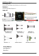
HS-872P User’s Manual Packing List: Please check the package material before you install the system.
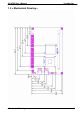
HS-872P User’s Manual Index Chapter 1 .................................................................... 6 1.1 .............................................................................. 6 1.2 ........................................................................ 7 1.3 < Mechanical Drawing > ........................................................................ 9 1.4 ..........................................................
HS-872P User’s Manual 2.15 ...................................................................... 36 Chapter 3 ........................................... 38 3.1
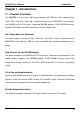
HS-872P User’s Manual Introduction Chapter 1 1.1 The HS-872P is an all-in-one single board computer with PISA bus. with supporting Intel Core 2 Duo / Core Duo / Core solo / Celeron M processor for 533/667MHz front side bus, Intel 945GM and ICH7-M chipset, integrated GMA950 graphics, DDR2 SDRAM memory, Realtek AC97 Audio, Serial ATA and two Intel 82573L Gigabit LAN .
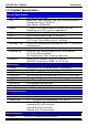
HS-872P User’s Manual Introduction 1.2 General Specification Form Factor CPU Half-size PISA CPU card Intel® Core 2 Duo/ Core Duo/ Core Solo/ Celeron M processor Package type: Micro- FCPGA478 Front side bus: 533/667MHz 1 x 240-pin DDR2 400/533/667MHz SDRAM up to 2GB Unbufferred, none-ECC memory supported only Intel® 945GM and ICH7-M Phoenix-Award v6.00PG 4Mb PnP flash BIOS Power saving mode includes doze, standby and suspend modes. ACPI version 1.0 and APM version 1.
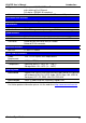
HS-872P User’s Manual Introduction Type Triple speed 10/100/1000Base-T auto-switching Fast Ethernet Full duplex, IEEE802.3U compliant Connector External two RJ45 connectors with LED on rear I/O panel Solid State Disk Interface Flash Type Compact Flash Type II for Compact Flash Card or Micro Drive ISA Interface ISA Bridge Function Winbond W83628G & W83629G I/O & IRQ supported only, no support DMA & bus mastering Audio Interface Chipset Interface Connector REALTEK ALC655 5.
HS-872P User’s Manual Introduction 1.
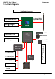
HS-872P User’s Manual Introduction 1.4 Intel Yonah Processor 1 x 240-pin DDR2 533/667MHz up to 2GB Intel GMA950 Graphics HDTV&LVDS&DVI 945GM 2 x SATA CompactFlash&IDE AC97 ALC655 4 x USB2.
HS-872P User’s Manual (This Page is Left for Blank) 11
HS-872P User’s Manual Hardware Setup Chapter 2 2.
HS-872P User’s Manual Hardware Setup CF PS2 Connector Location RJ45_1 RJ45_2 CRT 13
HS-872P User’s Manual Hardware Setup 2.2 2.2.
HS-872P User’s Manual Hardware Setup 2.
HS-872P User’s Manual Hardware Setup 2.4 < CPU and Memory Setup > 2.4.1 The board comes with the socket479 for Intel Core 2 Dual/Core Dual /Core solo processor, it supports new generation of Intel Core 2 Dual/Core Dual /Core solo processor with 533/667MHz of front side bus and 2MB L2 cache. Please follow the instruction to install the CPU properly. Unlock way 1. Use the flat-type screw drive to unlock the CPU socket Check point 2.
HS-872P User’s Manual Hardware Setup 2.4.2 HS-872P has one 240-pin DDR2 DIMM support up to 2GB of memory capacity. The memory frequency supports 533/667MHz. Only Non-ECC memory is supported. Dual-Channel technology is supported while applying two same modules on one of each group. Notice: When applying 2GB of memory, due to the memory resource issue, the available memory size would be less than 2GB.
HS-872P User’s Manual Hardware Setup 2.5 The board’s data of CMOS can be setting in BIOS. If the board refuses to boot due to inappropriate CMOS settings, here is how to proceed to clear (reset) the CMOS to its default values.
HS-872P User’s Manual Hardware Setup 2.6 The board has one Ultra ATA33 IDE interface to support up to 2 ATAPI devices, and one Compact Flash Type II socket on the solder side.
HS-872P User’s Manual Hardware Setup 2.7 Based on Intel ICH7-M, the board provides two Serial ATA interfaces with up to 150MB/s of transfer rate. SATA1/2 2.8 The Intel 82573L supports triple speed of 10/100/1000Base-T, with IEEE802.3 compliance and Wake-On-LAN supported.
HS-872P User’s Manual Hardware Setup 2.9 Based on Intel 945GM chipset with built-in GMA (Graphic Media Accelerator) 950 graphics, the board provides one DB15 connector on real external I/O port, and one 40-pin LVDS interface with 5-pin LCD backlight inverter connector. The board provides dual display function with clone mode and extended desktop mode for CRT and LCD and DVI and TV-out. 2.9.
HS-872P User’s Manual Hardware Setup 2.9.
HS-872P User’s Manual Connector: CN_INV Type: 5-pin LVDS Power Header Connector model: JST B5B-XH-A Pin 1 2 3 4 5 Description +12V GND GND GND ENABKL Hardware Setup Connector: JVLCD Type: 3-pin Power select Header Pin 1 2 3 Description VCC(5V) LCDVCC VCC3(3.3) Connector: CN_LVDS Type: onboard 40-pin connector for LVDS connector Connector model: HIROSE DF13-40DP-1.
HS-872P User’s Manual To setup the LCD, you need the component below: 1. A panel with LVDS interfaces. 2. An inverter for panel’s backlight power. 3. A LCD cable and an inverter cable. Hardware Setup For the cables, please follow the pin assignment of the connector to make a cable, because every panel has its own pin assignment, so we do not provide a standard cable; please find a local cable manufacture to make cables. LCD Installation Guide: 1.
HS-872P User’s Manual Hardware Setup 2.9.3 The board also comes with a DVI interface with Chrontel CH7307C for digital video interface. Connector: CN_DVI Connector type: 26-pin header connector (pitch = 2.
HS-872P User’s Manual Hardware Setup 2.9.4 The board provides an HDTV interface with Intel 945GM, supports PAL and NTSC of TV system, and display (clone or extended desktop) function with CRT,LVDS,DVI. Connector: CN_HDTV Connector type: 10-pin header HDTV connector (pitch = 2.
HS-872P User’s Manual Hardware Setup To connect the TV set, please follow the diagram below to setup your system: YPrPb Component Cable (For HDTV) TV-out Interface 27
HS-872P User’s Manual Hardware Setup After setup the devices well, you need to select the LCD panel type in the BIOS. The panel type mapping is list below: BIOS panel type selection form 18 bits Single channel NO. Output format NO.
HS-872P User’s Manual Hardware Setup 2.10 T The board provides the onboard AC97 5.1-channel audio interface with Realtek ALC655 Connector: CN_AUDIO Type: 10-pin (2 x 5) 1.27mm x 2.54mm-pitch header Pin Description Pin Description 1 LIN_L 2 Ground 3 LIN_R 4 MIC 2 5 MIC 2 6 Ground 7 N/C 8 FRONTL 9 FRONTR 10 Ground Connector: CDIN Type: 4-pin header (pitch = 2.
HS-872P User’s Manual Hardware Setup 2.11 Based on Intel ICH7-M , the board provides 4 USB2.0 ports. The USB2.0 interface provides up to 480Mbps of transferring rate. Interface USB2.0 Controller ICH7-M Transfer Rate Up to 480Mb/s Output Voltage 500mA CN_IR 1 5 CN_USB1/2 1 10 30 USB2.
HS-872P User’s Manual Connector: CN_IR Type: 5-pin header for SIR Port Pin Description 1 Vcc 2 N/C 3 IRRX 4 Ground 5 IRTX Connector: CN_USB1/2 Type: 10-pin (5 x 2) header for USB Port Pin Description 1 VCC 3 Data05 Data0+ 7 Ground 9 Ground Hardware Setup Pin 2 4 6 8 10 Description VCC Data1Data1+ Ground N/C PS: The USB2.0 will be only active when you connecting with the USB2.0 devices, if you insert an USB1.1 device, the port will be changed to USB1.1 protocol automatically.
HS-872P User’s Manual Hardware Setup 2.12 The board supports one RS232 serial port and one jumper selectable RS232/422/485 serial ports. The jumper JCSEL1 & JCSEL2 can let you configure the communicating modes for COM2. Connector: CN_COM1/2 Type: 10-pin (5 x 2) 2.54mm x 2.
HS-872P User’s Manual Hardware Setup CN_COM1 JCSEL1 10 JCSEL2 CN_COM2 1 2.13 The board comes with a 4-pin AT power connector for powering the board, three fan connectors for Northbridge, CPU and system. The board also provides a 3-pin ATX function connector. You can just connect the two power connectors without any backplane to work. 2.13.
HS-872P User’s Manual Hardware Setup 2.13.
HS-872P User’s Manual Hardware Setup 2.14 The board provides a 12-pin General Purpose I/O interface, with programmable 8-bit I/O (4-bit input & 4-bit output). Connector: CN_DIO Type: onboard 2 x 6-pin header, pitch=2.
HS-872P User’s Manual Hardware Setup 2.15 The JFRNT provides front control panel of the board, such as power button, reset and beeper, etc. Please check well before you connecting the cables on the chassis. Connector: JFRNT Type: onboard 14-pin (2 x 7) 2.
HS-872P User’s Manual (This Page is Left for Blank) 37
HS-872P User’s Manual System Configuration Chapter 3 3.1
HS-872P User’s Manual System Configuration Fixed + DVMT Memory Size: You can select the fixed amount and the DVMT amount at the same time for a guaranteed video memory and additional dynamic video memory, please check the table below for available setting.
HS-872P User’s Manual BIOS Setup Chapter 4 The motherboard uses the Award BIOS for the system configuration. The Award BIOS in the single board computer is a customized version of the industrial standard BIOS for IBM PC AT-compatible computers. It supports Intel x86 and compatible CPU architecture based processors and computers. The BIOS provides critical low-level support for the system central processing, memory and I/O sub-systems.
HS-872P User’s Manual (This Page is Left for Blank) 41
HS-872P User’s Manual I/O Port Pin Assignment Appendix A A.
HS-872P User’s Manual A.3 < Floppy Port > Connector: FDD Type: 26-pin connector Pin 1 3 5 7 9 11 13 15 17 19 21 23 25 Description VCC VCC VCC N/C N/C DRVDE0 N/C Ground Ground Ground N/C Ground Ground Pin 2 4 6 8 10 12 14 16 18 20 22 24 26 2 A.4 Connector: CN_COM1/2 Type: 10-pin (2 x 5) 2.
HS-872P User’s Manual I/O Port Pin Assignment 6 A.6 11 1 2 3 4 5 Connector: CRT Type: 15-pin D-sub female connector on bracket 12 13 14 15 10 Pin 1 2 3 4 5 Description RED GREEN BLUE N/C Ground Pin 6 7 8 9 10 Description Ground Ground Ground LVGA5V Ground Pin 11 12 13 14 15 Description N/C 5VCDA HSYNC VSYNC 5VCLK A.7 1 Connector: RJ45_1/2 Type: RJ45 connector with LED on rear panel Pin Description 1 TX+ 2 TX- 3 RX+ 4 N/C 8 5 N/C 6 RX- A.
HS-872P User’s Manual A.9 1 Connector: CN_ATKB Type: 5-pin box header 5 Pin Description 1 VCC 2 Ground 3 N/C 4 DATA 5 CLK A.10 1 Connector: PS2 Type: 6-pin Mini-DIN connector on bracket Pin Description 1 KBD 2 MSD 3 Ground 2 4 VCC 5 KBC 3 5 6 4 6 MSC Note: The PS/2 connector supports standard PS/2 keyboard directly or both PS/2 keyboard and mouse through the PS/2 Y-type cable.
HS-872P User’s Manual (This Page is Left for Blank) 46
HS-872P User’s Manual Flash BIOS Appendix B B.1 BIOS Auto Flash Tool The board is based on Award BIOS and can be updated easily by the BIOS auto flash tool. You can download the tool online at the address below: http://www.award.com http://www.commell.com.tw/support/support.htm TU UT TU UT File name of the tool is “awdflash.exe”, it’s the utility that can write the data into the BIOS flash ship and update the BIOS. B.2 Flash Method 1. Please make a bootable floppy disk. 2. Get the last .
HS-872P User’s Manual System Resources Appendix C C1.
HS-872P User’s Manual I/O Port Address Map System Resources 49
HS-872P User’s Manual System Resources C2.
HS-872P User’s Manual System Resources C3.
HS-872P User’s Manual Watch Dog timer Setting Appendix D The watchdog timer makes the system auto-reset while it stops to work for a period. The integrated watchdog timer can be setup as system reset mode by program.
HS-872P User’s Manual (This Page is Left for Blank) 53
HS-872P User’s Manual Contact Information Contact Information Any advice or comment about our products and service, or anything we can help you please don’t hesitate to contact with us. We will do our best to support you for your products, projects and business Taiwan Commate Computer Inc. Address 8F, No. 94, Sec. 1, Shin Tai Wu Rd., Shi Chih Taipei Hsien, Taiwan TEL +886-2-26963909 FAX +886-2-26963911 Website http://www.commell.com.tw E-Mail info@commell.com.