Intel® E8500 Chipset North Bridge (NB) and eXternal Memory Bridge (XMB) Thermal/Mechanical Design Guide March 2005 Document Number 306749-001
INFORMATION IN THIS DOCUMENT IS PROVIDED IN CONNECTION WITH INTEL® PRODUCTS. NO LICENSE, EXPRESS OR IMPLIED, BY ESTOPPEL OR OTHERWISE, TO ANY INTELLECTUAL PROPERTY RIGHTS IS GRANTED BY THIS DOCUMENT.
Contents 1 Introduction......................................................................................................................... 7 1.1 1.2 1.3 2 Packaging Technology ..................................................................................................... 11 2.1 3 Design Flow .........................................................................................................................7 Definition of Terms ...........................................................
8.5 8.6 XMB Heatsink Thermal Solution Assembly....................................................................... 38 8.5.1 Heatsink Orientation ........................................................................................... 39 8.5.2 Extruded Heatsink Profiles ................................................................................. 40 8.5.3 Mechanical Interface Material ............................................................................. 40 8.5.
Tables 3-1 3-2 6-1 6-2 A-1 A-2 A-3 B-1 Intel® E8500 Chipset NB Thermal Specifications ..............................................................15 Intel® E8500 Chipset XMB Thermal Specifications ...........................................................16 Chomerics THERMFLOW* T710 TIM Performance as a Function of Attach Pressure .....28 Reliability Guidelines..........................................................................................................29 NB Heatsink Thermal Solution #1 ....
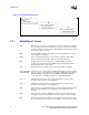
Revision History Document Number Revision Number 306749 001 Description • Initial release of this document Date March 2005 NOTE: Not all revisions may be published.
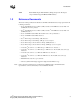
1 Introduction As the complexity of computer systems increases, so do the power dissipation requirements. Care must be taken to ensure that the additional power is properly dissipated. Typical methods to improve heat dissipation include selective use of ducting, and/or passive heatsinks.
Introduction Figure 1-1. Thermal Design Process 001239 1.2 8 Definition of Terms BGA Ball grid array. A package type, defined by a resin-fiber substrate, onto which a die is mounted, bonded and encapsulated in molding compound. The primary electrical interface is an array of solder balls attached to the substrate opposite the die and molding compound. BLT Bond line thickness. Final settled thickness of the thermal interface material after installation of heatsink. ICH5 I/O controller hub.
Introduction XMB 1.3 Intel® E8500 chipset eXternal Memory Bridge Component. The chipset component that bridges the IMI and DDR interfaces.
Introduction 10 Intel® E8500 Chipset North Bridge (NB) and eXternal Memory Bridge (XMB) Thermal/Mechanical Design Guide
2 Packaging Technology The E8500 chipsets consist of four individual components: the NB, the XMB, the Intel® 6700PXH 64-bit PCI Hub and the I/O controller hub (ICH5r). The E8500 chipset NB component use a 42.5 mm squared, 12-layer flip chip ball grid array (FC-BGA) package (see Figure 2-1 through Figure 2-3). The E8500 chipset XMB component uses a 37.5mm squared, 10-layer FB-BGA package (see Figure 2-4 through Figure 2-6).
Packaging Technology Figure 2-3. NB Package Dimensions (Bottom View) AV A U AT A R AP A N AM AL AK AJ A H AG AF A D AB AE A C AA Y W 42.5 + 0.05 V U T R P N M L 20.202 K J H G F E 37X 1.092 D C B A 1 2 3 4 5 6 7 8 9 10 11 12 13 14 15 16 17 18 19 20 21 22 23 24 25 26 27 28 29 30 31 32 33 34 35 36 37 38 A 37X 1.092 20.202 42.5 + 0.05 0.2 C A B NOTES: 1. All dimensions are in millimeters. 2. All dimensions and tolerances conform to ANSI Y14.5M-1994.
Packaging Technology Figure 2-4. XMB Package Dimensions (Top View) Handling Exclusion Area Die Keepout Area 14.02mm. 8.88mm. XMB Die 11.73mm. 6.65mm. 23.50mm. 27.50mm. 37.50mm. 23.50mm. 27.50mm. 37.50mm. Figure 2-5. XMB Package Dimensions (Side View) Substrate 2.535 ± 0.123 mm 2.100 ± 0.121 mm Decoup Cap 0.84 ± 0.05 mm Die 0.7 mm Max 0.20 See Note 4 0.20 0.435 ± 0.025 mm See Note 3 –C– Seating Plane See Note 1 Notes: 1.
Packaging Technology Figure 2-6. XMB Package Dimensions (Bottom View) AV A U AT A R AP A N AM AL AK AJ A H AG AF A D AB AE A C AA Y W 42.5 + 0.0 V U T R P N M L 20.202 K J H G F E 37X 1.092 D C B A 1 2 3 4 5 6 7 8 9 10 11 12 13 14 15 16 17 18 19 20 21 22 23 24 25 26 27 28 29 30 31 32 33 34 35 36 37 38 A 37X 1.092 20.202 42.5 + 0.05 0.2 C A 2.
3 Thermal Specifications 3.1 Thermal Design Power (TDP) Analysis indicates that real applications are unlikely to cause the E8500 chipset NB/XMB components to consume maximum power dissipation for sustained time periods. Therefore, in order to arrive at a more realistic power level for thermal design purposes, Intel characterizes power consumption based on known platform benchmark applications. The resulting power consumption is referred to as the Thermal Design Power (TDP).
Thermal Specifications Table 3-2. Intel® E8500 Chipset XMB Thermal Specifications Parameter Value Tcase_max 105°C Tcase_min 5°C Notes TDPdual channel 9.1W DDR-266 TDPdual channel 9.3W DDR-333 TDPdual channel 8.5W DDR2-400 NOTE: 1. These specifications are based on silicon characterization, however, they may be updated as further data becomes available.
4 Thermal Simulation Intel provides thermal simulation models of the E8500 chipset NB/XMB components and associated user's guides to aid system designers in simulating, analyzing, and optimizing their thermal solutions in an integrated, system-level environment. The models are for use with the commercially available Computational Fluid Dynamics (CFD)-based thermal analysis tool FLOTHERM* (version 3.1 or higher) by Flomerics, Inc. These models are also available in ICEPAK* format.
Thermal Simulation 18 Intel® E8500 Chipset North Bridge (NB) and eXternal Memory Bridge (XMB) Thermal/Mechanical Design Guide
5 Thermal Metrology The system designer must make temperature measurements to accurately determine the thermal performance of the system. Intel has established guidelines for proper techniques to measure the NB/XMB die temperatures. Section 5.1 provides guidelines on how to accurately measure the NB/XMB die temperatures. Section 5.2 contains information on running an application program that will emulate anticipated maximum thermal design power.
Thermal Metrology Figure 5-1. Thermal Solution Decision Flowchart 001240 Figure 5-2. Zero Degree Angle Attach Heatsink Modifications NOTE: Not to scale. Figure 5-3. Zero Degree Angle Attach Methodology (Top View) Die Thermocouple Wire Cement + Thermocouple Bead Substrate 001321 NOTE: Not to scale.
Thermal Metrology 5.2 Power Simulation Software The power simulation software is a utility designed to dissipate the thermal design power on an E8500 chipset NB component or XMB component when used in conjunction with the 64-bit Intel® Xeon™ processor MP. The combination of the above mentioned processor and the higher bandwidth capability of the E8500 chipsets enable higher levels of system performance.
Thermal Metrology 22 Intel® E8500 Chipset North Bridge (NB) and eXternal Memory Bridge (XMB) Thermal/Mechanical Design Guide
6 NB Reference Thermal Solution #1 Intel has developed two different reference thermal solutions designed to meet the cooling needs of the E8500 chipset NB component under operating environments and specifications defined in this document. This chapter describes the overall requirements for the 1st NB reference thermal solution including critical-to-function dimensions, operating environment, and validation criteria.
NB Reference Thermal Solution #1 Figure 6-1. First NB Reference Heatsink Measured Thermal Performance vs. Approach Velocity 1.50 Ȍ Ȍca (°C/W) 1.40 1.30 1.20 1.10 1.00 0.90 0.80 100 200 300 400 500 600 700 Flow Rate (LFM) 6.3 Mechanical Design Envelope While each design may have unique mechanical volume and height restrictions or implementation requirements, the height, width, and depth constraints typically placed on the E8500 chipset NB thermal solution are shown in Figure 6-2.
NB Reference Thermal Solution #1 4 .2 9 m m . 4 mm. H e a ts in k F in 5 5.0 9 m m . Figure 6-2. First NB Reference Heatsink Volumetric Envelope H e a ts in k B a s e IH S + T IM 2 F C B G A + S o ld e r B a lls M o th e rb o a rd 6 4 .5 2 m m . 4 2 .5 0 m m . 64 .5 2 m m . H e a ts in k F in 42 .5 0 m m . TNB H e a ts in k H e a ts in k B a s e 6.
NB Reference Thermal Solution #1 6.5 First NB Heatsink Thermal Solution Assembly The reference thermal solution for the chipset NB component is a passive extruded heatsink with thermal interface. It is attached to the board by using four retaining Tuflok* fasteners. Figure 6-4 shows the reference thermal solution assembly and associated components. Full mechanical drawings of the thermal solution assembly and the heatsink are provided in Appendix B.
NB Reference Thermal Solution #1 6.5.1 Heatsink Orientation Since this solution is based on a unidirectional heatsink, mean airflow direction must be aligned with the direction of the heatsink fins. Figure 6-4. First NB Heatsink Assembly 6.5.2 Extruded Heatsink Profiles The reference NB thermal solution uses an extruded heatsink for cooling the chipset NB. Figure 6-5 shows the heatsink profile. Appendix A lists a supplier for this extruded heatsink.
NB Reference Thermal Solution #1 the thermal resistance of the Chomerics THERMFLOW T710 TIM is shown in Table 6-1 The heatsink clip provides enough pressure for the TIM to achieve a thermal conductivity of 0.17°C inch2/W. Table 6-1. Chomerics THERMFLOW* T710 TIM Performance as a Function of Attach Pressure Pressure (psi) Thermal Resistance (°C × in2)/W 5 0.37 10 0.30 20 0.21 30 0.17 NOTE: 1. All measured at 50°C. 6.5.
NB Reference Thermal Solution #1 6.6 Reliability Guidelines Each motherboard, heatsink and attach combination may vary the mechanical loading of the component. Based on the end user environment, the user should define the appropriate reliability test criteria and carefully evaluate the completed assembly prior to use in high volume. Some general recommendations are shown in Table 6-2. Table 6-2.
NB Reference Thermal Solution #1 30 Intel® E8500 Chipset North Bridge (NB) and eXternal Memory Bridge (XMB) Thermal/Mechanical Design Guide
7 NB Reference Thermal Solution #2 Intel has developed two different reference thermal solutions designed to meet the cooling needs of the E8500 chipset NB component under operating environments and specifications defined in this document. This chapter describes the overall requirements for the 2nd NB reference thermal solution including critical-to-function dimensions, operating environment, and validation criteria.
NB Reference Thermal Solution #2 Figure 7-1. Second NB Reference Heatsink Measured Thermal Performance vs. Approach Velocity 2.3 Ȍca (°C/W) 2 1.7 1.4 1.1 0.8 0.5 0 100 200 300 400 500 600 Flow Rate (LFM) 7.3 Mechanical Design Envelope While each design may have unique mechanical volume and height restrictions or implementation requirements, the height, width, and depth constraints typically placed on the E8500 chipset NB thermal solution are shown in Figure 7-2.
NB Reference Thermal Solution #2 4 .2 9 m m . 4 mm. H e a t s in k F in 5 5 .0 9 m m . Figure 7-2. Second NB Reference Heatsink Volumetric Envelope H e a t s in k B a s e IH S + T IM 2 FCBGA M o th e r b o a r d 6 4 .5 2 m m . 4 2 .5 0 m m . H e a t s in k F in 7.4 6 4 .5 2 m m . 4 0 .5 0 m m . H e a t s in k B a s e Board-Level Components Keepout Dimensions Please refer to Section 6.4 for detail. 7.
NB Reference Thermal Solution #2 Figure 7-3. Second NB Heatsink Assembly 7.5.1 Heatsink Orientation Since this solution is based on a unidirectional heatsink, mean airflow direction must be aligned with the direction of the heatsink fins. 7.5.2 Extruded Heatsink Profiles Please refer to Section 6.5.2 for detail. 7.5.3 Mechanical Interface Material There is no mechanical interface material associated with this reference solution. 7.5.4 Thermal Interface Material Please refer to Section 6.5.
NB Reference Thermal Solution #2 7.6 Reliability Guidelines Please refer to Section 6.6 for detail.
NB Reference Thermal Solution #2 36 Intel® E8500 Chipset North Bridge (NB) and eXternal Memory Bridge (XMB) Thermal/Mechanical Design Guide
8 XMB Reference Thermal Solution Intel has developed one different reference thermal solution designed to meet the cooling needs of the E8500 chipset XMB component under operating environments and specifications defined in this document. This chapter describes the overall requirements for the XMB reference thermal solution including critical-to-function dimensions, operating environment, and validation criteria.
XMB Reference Thermal Solution 8.3 Mechanical Design Envelope While each design may have unique mechanical volume and height restrictions or implementation requirements, the height, width and depth constraints typically placed on the E8500 chipset XMB thermal solution are showing in Figure 8-2. When using heatsinks that extend beyond the XMB reference heatsink envelope shown in Figure 8-2, any motherboard components placed between the heatsink and motherboard cannot exceed 2.48 mm (0.10 in.) in height.
XMB Reference Thermal Solution Full mechanical drawings of the thermal solution assembly and the heatsink are provided in Appendix B. Appendix A contains vendor information for each thermal solution component. Figure 8-3. XMB Heatsink Board Component Keepout 63.500mm. 55.250mm. 37.500mm. 37.5mm XMB Location 38.097mm. 48.260mm. 4X Ø 5.5mm 4X Ø 2.95 ± 0.0254mm No Component Keep Out Area 2.48mm Max Component Height Heatsink Mounting Hole 8.5.
XMB Reference Thermal Solution 8.5.2 Extruded Heatsink Profiles The reference XMB thermal solution uses an extruded heatsink for cooling the chipset XMB. Figure 8-5 shows the heatsink profile. Appendix A lists a supplier for this extruded heatsink. Other heatsinks with similar dimensions and increased thermal performance may be available. A full mechanical drawing of this heatsink is provided in Appendix B. 8.5.
XMB Reference Thermal Solution Figure 8-5. XMB Heatsink Extrusion Profile 8.6 Reliability Guidelines Please refer to Section 6.6 for detail.
XMB Reference Thermal Solution 42 Intel® E8500 Chipset North Bridge (NB) and eXternal Memory Bridge (XMB) Thermal/Mechanical Design Guide
A Thermal Solution Component Suppliers Table A-1. NB Heatsink Thermal Solution #1 Part Heatsink Assembly includes: Intel Part Number Supplier (Part Number) C23120-001 CCI/ACK • Unidirectional Fin Heatsink Contact Information Harry Lin (USA) 714-739-5797 hlinack@aol.com • Thermal Interface Material • Retaining Fastener Monica Chih (Taiwan) 866-2-29952666, x131 monica_chih@ccic.com.tw Unidirectional Fin Heatsink (64.52 x 64.52 x 50.
Thermal Solution Component Suppliers Table A-2. NB Heatsink Thermal Solution #2 Part Heatsink Assembly includes: Intel Part Number Supplier (Part Number) C44148-001 CCI/ACK • Unidirectional Fin Heatsink Contact Information Harry Lin (USA) 714-739-5797 hlinack@aol.com • Thermal Interface Material • Retaining Fastener Monica Chih (Taiwan) 866-2-29952666, x131 monica_chih@ccic.com.tw Unidirectional Fin Heatsink (64.52 x 64.52 x 50.
Thermal Solution Component Suppliers Table A-3. XMB Heatsink Thermal Solution Retaining Fastener - ITW Fastex* (8034-00-9909) Ron Schmidt (USA) 847-299-2222 rschmidt@itwfastex.com Henry Lu (Taiwan) (886) 7-811-9206 Ext. 10 henry@mail.itwasia.com.tw Note: The enabled components may not be currently available from all suppliers. Contact the supplier directly to verify time of component availability.
Thermal Solution Component Suppliers 46 Intel® E8500 Chipset North Bridge (NB) and eXternal Memory Bridge (XMB) Thermal/Mechanical Design Guide
B Mechanical Drawings Table B-1.
Mechanical Drawings Figure B-1.
Mechanical Drawings Figure B-2.
Mechanical Drawings Figure B-3.
Mechanical Drawings Figure B-4.
Mechanical Drawings Figure B-5.
Mechanical Drawings Figure B-6.
Mechanical Drawings § 54 Intel® E8500 Chipset North Bridge (NB) and eXternal Memory Bridge (XMB) Thermal/Mechanical Design Guide