
User's Manual

Chapter 5 Installation
AI5VG Pentium VP3 Baby AT Motherboard User’s Manual 21
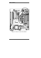
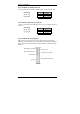
5.1 I/O Connectors
The I/O connectors connect the AI5VG to the most common peripherals.
To attach cables to these connectors, carefully align Pin 1 of the cables to
that of the connectors. Refer to Figure 4 for the location and orientation
of the connectors.
Figure 4: Orientation of the I/O Connector
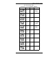
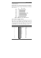
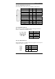
5.2 J3: AT Power Supply Connector
When using an AT compatible power supply, plug both of the power
supply connectors into J3. Make sure the power supply connectors are
connected in the right orientation. The power supply connectors are
connected in the right orientation if the black wires of each power cable
are ADJACENT to each other. That is, black wires of each connector
should be aligned in the center of the J3 power supply connector.
J3 Pin # Description Wire Color
1
Θ
Power Good Orange
2
●
+5V Red
3
●
+12V Yellow
4
●
-12V Blue
5
●
Ground Black
6
●
Ground Black
7
Θ
Ground Black
8
●
Ground Black
9
●
-5V White
10
●
+5V Red
11
●
+5V Red
12
●
+5V Red