
User's Manual

Chapter 5 Installation
AI5VG Pentium VP3 Baby AT Motherboard User’s Manual 19
Chapter 5 Installation
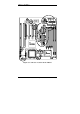
This chapter describes the connectors and interfaces that the AI5VG
provides for creating a working system. Refer to Figure 3 for the location
of the connectors.
The following items are covered in this chapter:
5.1 I/O Connectors..........................................................................21
5.2 J3: AT Power Supply Connector...............................................21
5.3 J2: ATX Power Supply Connector............................................22
5.4 J1, J4: AT Keyboard and PS/2 Mouse Connectors...................22
5.5 J7, J6: Serial Ports.....................................................................23
5.6 J8: Floppy Drive Connector......................................................23
5.7 J9, J11: EIDE Connectors.........................................................24
5.8 J10: Parallel Port Connector .....................................................25
5.9 J15: IrDA Connector.................................................................25
5.10 J5: USB Connector..................................................................25
5.11 J13 Wake on LAN Connector.................................................26
5.12 J14: CPU Fan Power Connector..............................................26
5.13 J20 Front Bezel Connector......................................................26