ADE-6050 Intel Core Duo/Solo 945GM Mini ITX Board User’s Manual Rev. 1.
ADE-6050 User’s Manual Copyright All rights reserved. The information contained in this guide has been validated and reviewed for accuracy. No patent liability is assumed with respect to the use of the information contained herein. While every precaution has been taken in the preparation of this guide, the Manufacturer assumes no responsibility for errors or omissions.
ADE-6050 User’s Manual How to Use This Manual This manual is written for the system integrator, PC technician and knowledgeable PC end user. It describes how to configure your system board to meet various operating requirements. The user’s manual is divided into four chapters, with each chapter addressing a basic concept and operation of the server board.
ADE-6050 User’s Manual Table of Content 1. Introduction ..........................................................................................................................8 1.1 Description .......................................................................................................................8 1.2 Packing Check List.........................................................................................................9 1.3 Specifications .........................................
ADE-6050 User’s Manual 3. System Installation .........................................................................................................23 3.1 Socket 478 Processors................................................................................................23 3.1.1 Installing CPU ..........................................................................................................23 3.2 Installing Cooling Fan.........................................................................
ADE-6050 User’s Manual 6 / 48
ADE-6050 User’s Manual CHAPTER 1 7 / 48
ADE-6050 User’s Manual 1. Introduction 1.1 Description The ADE-6050 all-in-one Mini-ITX is designed to fit a high performance IntelR CoreTM Duo based processor and compatible for high-end computer system applications with PCI bus architecture to meet today’s demanding pace and keep complete compatibility with hardware and software designed. The onboard devices support one PCI Express x1 and one PCI slot, integrated graphics, and onboard dual Marvell Gigabit Ethernet controllers.
ADE-6050 User’s Manual 1.2 Packing Check List The ADE-6050 package includes the following basic items accompany with this manual.
ADE-6050 User’s Manual 1.
ADE-6050 User’s Manual Audio AC97 Codec Realtek® ALC655 5.1CH 3D audio codec Audio Interface Ethernet Line in, Line out, Mic in by jack, CD-in by pin header Chipset Dual Marvell® 88E8053 PCI-E Gigabit Ethernet controllers Ethernet Interface IEEE 802.3 10/100/1000 BASE-TX Mechanical & Environmental Power Requirement +3.3V@0.32A, +5V@2.67A, +12V@2.13A. 5VSB@0.
ADE-6050 User’s Manual 1.4 System Architecture All of details operating relations are shown in ADE-6050 system block diagram. Micro FCPGA for Intel Core Duo/ Solo Processor IMVP6 CK-410M 533/667 MHz FSB LVDS & VGA CRT & LCD GMCH (945GM) 1466 FCBGA DDR2 SO- DIMM 533/667 X2 DVI DMI Bus ATA100 IDE Primary SATA P o r t 1 / 2 USB Port 1/2/3/4 PCI BUS SATAII USB2.
ADE-6050 User’s Manual 1.5 Dimensions 33.0 132.1 0 10.51 163.7 78.51 G 106.17 G 128.61 6.5 6.2 146.35 22.0 35.5 10.2 170 Unit: mm 13 / 48 170 39.
ADE-6050 User’s Manual CHAPTER 2 14 / 48
ADE-6050 User’s Manual 2. Hardware Configuration Setting This chapter gives the definitions and shows the positions of jumpers, headers and connectors. All of the configuration jumpers on the board are in the proper position. The default settings shipped from factory are marked with an asterisk («). In general, jumpers on the board are used to select options for certain features. Some of the jumpers are designed to be user-configurable, allowing for system enhancement.
ADE-6050 User’s Manual 2.1 Board Layout 95P08 DVI AUDIO COM1 KB/MS CN3 CN1 CN2 CN8 LAN2 USB2 / 3 CD - IN CN5 CN7 CN6 JP1 CN11 CN12 USB6/ 7 USB4 / 5 EXT.
ADE-6050 User’s Manual 2.
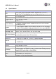
ADE-6050 User’s Manual 2.3 Jumpers- Setting & Connectors description 2.3.1 LCD power setting select: JP1 PIN No. Description 1-2 3.3V« 2-3 5V 2.3.2 Clear CMOS setting select: JP2 2.3.3 Auto power on select: JP3 2.3.4 BIOS write protection setting: JP4 PIN No. Description 1-2 Normal operation « 2-3 Clear CMOS PIN No. Description PIN No. Description 1-2 Auto power on 1-2 Write-protection (Default) « Open Disabled« 2-3 Disable 2.3.5 Audio connector: CN1 PIN No. 2.3.
ADE-6050 User’s Manual 2.3.9 LAN 1 + USB 0/1 & LAN 2 + USB 2/3 Connectors: CN6 & CN5 LAN 1/2 USB 0/1/2/3 PIN No. Description PIN No. Description PIN No. Description PIN No. Description 1 MDI0+ 5 MDI2+ 1 +5 V (fused) 5 +5 V (fused) 2 MDI0- 6 MDI2- 2 USBP0-/2- 6 USBP1-/3- 3 MDI1+ 7 MDI3+ 3 USBP0+/2+ 7 USBP1+/3+ 4 MDI1- 8 MDI3- 4 Ground 8 Ground 2.3.10 Internal USB 4/5 & 6/7 Connectors: CN12 & CN11 Description PIN No. PIN No.
ADE-6050 User’s Manual 2.3.13 Line out Connector: CN9 2.3.14 LVDS Connector: CN10 PIN No. 1 Description NC PIN No.
ADE-6050 User’s Manual 2.3.19 8-bit Digital I/O Connector: CN20 Description EXT_VDD O1 O2 O3 O4 PIN No. 1 3 5 7 9 PIN No. 2 4 6 8 10 Description Description Reset IDE Host Data 7 Host Data 6 Host Data 5 Host Data 4 Host Data 3 Host Data 2 Host Data 1 Host Data 0 Ground DRQ 0 Host IOW Host IOR IOCHRDY DACK 0 IRQ 14 Address 1 Address 0 Chip Select 0 Activity PIN No. 2 4 6 8 10 12 14 16 18 20 22 24 26 28 30 32 34 36 38 40 Description I1 I2 I3 I4 EXT_VSS 2.3.21 Primary IDE Connector: IDE1 PIN No.
ADE-6050 User’s Manual CHAPTER 3 22 / 48
ADE-6050 User’s Manual 3. System Installation This chapter provides you with instructions on ho w to setup your system. The additional information shows you how to install CPU / FAN and memory. 3.1 Socket 478 Processors 3.1.1 Installing CPU w w w w Check and confirm that you are going to install correctly CPU type and pin numbers. Take the screwdriver and releasing screw-nut of the socket 478. Rotate mark of screw-nut to face the “OPEN”.
ADE-6050 User’s Manual 3.3 Main Memory The figures display the notch marks and what they should look like on your SO-DIMM memory module. SO-DIMM has 200-pins and two notches, that will match with the onboard SO-DIMM socket. Memory modules are installed by placing the chip firmly into the socket at a parallel angle and pressing straight down until it fits tightly into the SO-DIMM socket.
ADE-6050 User’s Manual CHAPTER 4 25 / 48
ADE-6050 User’s Manual 4. BIOS Setup 4.1 Entering Setup PHOENIX-AWARD™ has a built-in setup program that allows users to modify the basic system configuration. This information is stored in CMOS RAM whose power is supplied by a battery so that it can retain the setup information even when the power is turned off. Press the key “Delete” when you Power on or Reboot the computer system. (i.e. After the logo appears at the center of the screen, please press Delete to enter the BIOS setup program).
ADE-6050 User’s Manual 4.2.1 Standard CMOS Features 4.2.1.1 Date (mm/date/year): Set the system date. Note that the ‘Day’automatically changes when you set the date. 4.2.1.2 Time (hh/mm/ss): Set the system time. 4.2.1.3 IDE Channel 0 / 1 Master: Press to enter the sub menu of detailed options. 4.2.1.4 IDE Channel 0 / 1 Slave: Press to enter the sub menu of detailed options. 4.2.1.5 SATA Channel 1 / 2: Press to enter the sub menu of detailed options. 4.2.1.
ADE-6050 User’s Manual 4.2.1.7 Halt On: Select the situation in which you want the BIOS to stop the POST process and notify you. The Choice: All Errors/No Errors/All, but Keyboard/All, but Diskette/ All, but Disk/Key. 4.2.1.8 Base Memory: Displays the amount of conventional memory detected during boot up. 4.2.1.9 Extended Memory: Displays the amount of extended memory detected during boot up. 4.2.1.10 Total Memory: Displays the total memory available in the system. 4.2.
ADE-6050 User’s Manual 4.2.2.1 CPU Feature 4.2.2.1.1 Delay Prior to Thermal: Select this item allows the delay prior to thermal time. The Choice: Auto, 4, 8, 16, 32Min. 4.2.2.1.2 Execute Disable Bit: Select when disable, forces the XD feature flag to always return 0. The choice: Enabled, Disabled. 4.2.2.2 Virus Warning: Allow you to choose the VIRUS Warning feature for IDE Hard Disk boot sector protection.
ADE-6050 User’s Manual 4.2.2.4 Quick Power On Self Test This category speeds up Power On Self Test (POST) after you power up the computer. If it is set to Enable, BIOS will shorten or skip some check items during POST. The choice: Enabled, Disabled. 4.2.2.5 Boot Up NumLock Status Select power on state for NumLock. The choice: On, Off. 4.2.2.6 Gate A20 Option Select if chipset or keyboard controller should control GateA20. The choice: Normal, Fast. 4.2.2.
ADE-6050 User’s Manual 4.2.2.13 OS Select For DRAM > 64MB Select the operating system that is running with greater than 64MB of RAM on the system. The choice: Non-OS2, OS2. 4.2.2.14 Cache Setup 4.2.2.14.1 CPU L1& L2 Cache These two categories speed up memory access. However, it depends on CPU/chipset design. The choice: Enabled, Disabled. 4.2.2.14.2 CPU L3 Cache The option enables Level 3 cache memory. However, it depends on CPU/chipset design. The choice: Enabled, Disabled.
ADE-6050 User’s Manual 4.2.2.15 Boot Seq & Floppy Setup 4.2.2.15.1 Hard Disk Boot Priority Press Enter and It shows Bootable add-in Card. 4.2.2.15.2 First/Second/Third Boot Device The BIOS attempts to load the operating system from the devices in the sequence selected in these items. The choice: Floppy, LS/ZIP, HDD, SCSI, CDROM, LAN and Disabled. 4.2.2.15.
ADE-6050 User’s Manual 4.2.3 Advanced Chipset Features 4.2.3.1 DRAM Timing Selectable Select the operating system that is selecting DRAM timing, so select SPD for setting SDRAM timing by SPD. The Choice: Manual, By SPD. 4.2.3.2 CAS Latency Time When synchronous DRAM is installed, the number of clock cycles of CAS latency depends on the DRAM timing. 4.2.3.3 DRAM RAS# to CAS# Delay The system board designer should set the values in this field, depending on the DRAM installed.
ADE-6050 User’s Manual 4.2.3.4 DRAM RAS# Precharge If an insufficient number of cycles are allowed for the RAS to accumulate its charge before DRAM refresh, the refresh may be incomplete and the DRAM may fail to retain data. Fast gives faster performance; and Slow gives more stable performance. This field applies only when synchronous DRAM is installed in the system. 4.2.3.5 Precharge Delay (tRAS) Select the operating system that is active to precharge delay. 4.2.3.
ADE-6050 User’s Manual 4.2.3.10 PCI Express Root Port Function 4.2.3.10.1 PCI Express x1 Slot This item allows you to active PCI Express. The choice: Auto, Enabled, Disabled. 4.2.3.10.2 PCI-E Compliancy Mode This item allows you to choose PCI-E Compliancy Mode. The choice: v1.0a, v1.0. 4.2.3.11 PEG/Onchip VGA Control This item allows you to control the PEG or on-chip VGA. The choice: Onchip VGA, PEG Port, Auto. 4.2.3.
ADE-6050 User’s Manual 4.2.3.14 DVMT/FIXED Memory Size This item allows you to select the DVMT or FIXED memory size. 4.2.3.15 Boot Display This item allows you to select the boot display device. 4.2.3.16 Panel Scaling This item allows you to enable or disable the Scaling function. The choice: AUTO, ON, OFF. 4.2.3.17 Panel Number This item allows you to select the panel resolution that will be displayed depending on the LCD panel (LFP). 4.2.
ADE-6050 User’s Manual 4.2.4.1 Onchip IDE Device 4.2.4.2.1. IDE HDD Block Mode Block mode is also called block transfer, multiple commands, or multiple sector read/write. If your IDE hard drive supports block mode (most new drives do), select Enabled for automatic detection of the optimal number of block read/writes per sector the drive can support. The choice: Enabled, Disabled. 4.2.4.2.2.
ADE-6050 User’s Manual 4.2.4.2.4. IDE Primary/Secondary Master/Slave PIO The four IDE PIO (Programmed Input/Output) fields let you set a PIO mode (0-4) for each of the four IDE devices that the onboard IDE interface supports. Modes 0 throug h 4 provide successively increased performance. In Auto mode, the system automatically determines the best mode for each device. The choice: Auto, Mode 0, Mode 1, Mode 2, Mode 3 and Mode 4. 4.2.4.2.5.
ADE-6050 User’s Manual 4.2.4.2 Onboard Device 4.2.4.2.1. Onboard Giga Lan 2 Select “Enabled” if your system has a LAN device installed on the system board and you wish to use it. The choice: Auto, Enabled, Disabled. 4.2.4.2.2. USB Controller Select “Enabled” if your system contains a Universal Serial Bus (USB) controller and you have USB peripherals. The choice: Enabled, Disabled. 4.2.4.2.3. USB 2.0 Controller Select “Enabled” if your system contains a Universal Serial Bus 2.0 (USB 2.
ADE-6050 User’s Manual 4.2.4.2.5. USB Mouse Support Select “Enabled” if your system contains a Universal Serial Bus (USB) controller and you have a USB mouse. The choice: Enabled, Disabled. 4.2.4.2.6. Azalia/AC97 Audio Select This item allows you to select the chipset family to support AC97 Audio The choice: Auto, Azalia, AC97 Audio only, All disabled. 4.2.4.3 Super IO Device 4.2.4.2.1. Onboard Serial Port 1/2 Select an address and corresponding interrupt for the first and second serial ports.
ADE-6050 User’s Manual 4.2.4.2.3. UR2 Duplex Mode Select the value required by the IR device connected to the IR port. Full-duplex mode permits simultaneous two-direction transmission. Half-duplex mode permits transmission in one direction only at a time. The choice: Half, Full. 4.2.4.2.4. PWRON After PWR-Fail This item allows you to select if you want to power on the system after power failure. The choice: Off, On and Former-Sts. 4.2.5 Power Management Setup 4.2.5.
ADE-6050 User’s Manual 4.2.5.3 Power Management This category allows you to select the type (or degree) of power saving and is directly related to the following modes: 1. HDD Power Down, 2. Doze Mode, 3. Suspend Mode Min. Power Saving: Minimum power management. Doze Mode = 1 hr. Standby Mode = 1 hr., Suspend Mode = 1 hr., and HDD Power Down = 15 min. Max. Power Saving: Maximum power management -- ONLY AVAILABLE FOR SL CPU’s. Doze Mode = 1 min., Standby Mode = 1 min., Suspend Mode = 1 min.
ADE-6050 User’s Manual 4.2.5.8 HDD Power Down When “Enabled” and after the set time of system inactivity, the ha rd disk drive will be powered down while all other devices remain active. The choice: Disabled, 1~15Min. 4.2.5.9 Sort-Off by PWR-BTTN Pressing the power button for more than 4 seconds forces the system to enter the Soft-Off state when the system has “hung. The choice: Delay 4 Sec, Instant-Off. 4.2.5.
ADE-6050 User’s Manual 4.2.6 PnP/PCI/PCI-E Configurations 4.2.6.1 Init Display First This item allows you to decide to active whether PCI Slot or on-chip VGA first. 4.2.6.2 Reset Configuration Data Normally, you leave this field Disabled. Select “Enabled” to reset Extended System Configuration Data (ESCD) when you exit Setup if you have installed a new add-on and the system reconfiguration has caused such a serious conflict that the operating system cannot boot. The choice: Enabled, Disabled. 4.2.6.
ADE-6050 User’s Manual 4.2.6.3.1 IRQ Resources When resources are controlled manually, assign each system interrupt a type, depending on the type of device using the DMA channel. 4.2.6.4 PCI/VGA Palette Snoop This function determines if the graphics card should allow VGA palette snooping by a fixed function display card. It is only useful if a fixed-function display card using that requires a VGA-compatible graphics card to be present. Otherwise, leave the setting as default Disabled.
ADE-6050 User’s Manual 4.2.7.2 Vcore The voltage level of CPU (Vcore). 4.2.7.3 +3.3V/+5V/+12V/-12V/5Vsb Show you the voltage of +3.3V/+5V/+12V/-12V. 4.2.7.4 Voltage Battery Show you the voltage level of the battery. 4.2.7.5 System/CPU Temperature Show you the current system/CPU temperature. 4.2.7.6 System/CPU FAN Speed Show you the current System/CPU FAN operating speed. 4.2.
ADE-6050 User’s Manual 4.2.10 Supervisor/User Password Setting You can set either supervisor or user password, or both of then. The differences between are: Set Supervisor Password: can enter and change the options of the setup menus. Set User Password: just can only enter but do not have the right to change the options of the setup menus. When you select this function, the following message will appear at the center of the screen to assist you in creating a password.
ADE-6050 User’s Manual 4.2.11 Exit Selecting Save & Exit Setup Pressing on this item asks for confirmation: Save to CMOS and EXIT (Y/N)? Y Pressing “Y” stores the selections made in the menus in CMOS – a special section of memory that stays on after you turn your system off. The next time you boot your computer, the BIOS configures your system according to the Setup selections stored in CMOS. After saving the values the system is restarted again.