
User's Manual

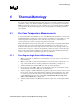
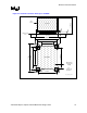
Table Of Contents
- Contents
- Figures
- Tables
- Revision History
- Introduction
- Packaging Technology
- Thermal Specifications
- Thermal Simulation
- Thermal Metrology
- Reference Thermal Solution
- Appendix A: Thermal Solution Component Suppliers
- Appendix B: Mechanical Drawings
Reference Thermal Solution
R
20 Intel
®
955X Express Chipset Thermal/Mechanical Design Guide
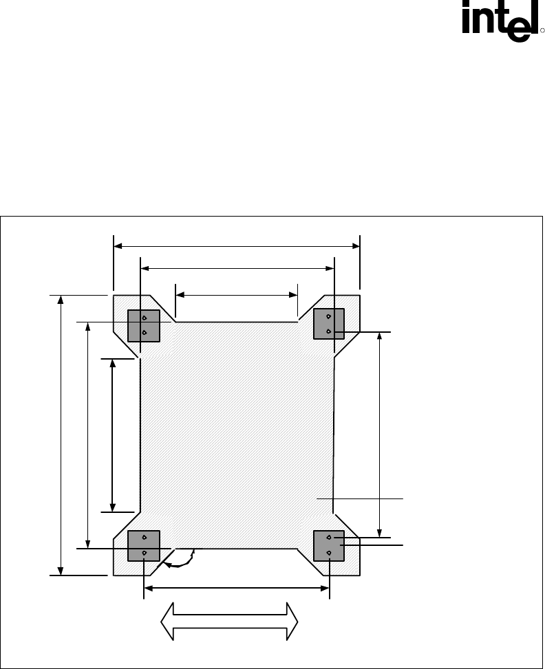
6.4 Board-Level Components Keep-out Dimensions
The location of hole patterns and keep-out zones for the reference thermal solution are shown in
Figure 6-3 and Figure 6-4.
Figure 6-3. MCH Heatsink Board Component Keep-out
TN B
Heatsink Fin
26.79 mm
48.0 mm
60.6 mm
47.0 mm
135
O
45.79 mm
67.0 mm
81.0 mm
60.92 mm
Max 2.2 mm
Component
Height
No
component
this Area
Air Flow
HS_Brd_Component_Keepout