R Intel® 955X Express Chipset Thermal/Mechanical Design Guide – For the Intel® 82955X Memory Controller Hub (MCH) April 2005 Document Number: 307012-001
R INFORMATION IN THIS DOCUMENT IS PROVIDED IN CONNECTION WITH INTEL® PRODUCTS. NO LICENSE, EXPRESS OR IMPLIED, BY ESTOPPEL OR OTHERWISE, TO ANY INTELLECTUAL PROPERTY RIGHTS IS GRANTED BY THIS DOCUMENT.
R Contents 1 Introduction ......................................................................................................................... 7 1.1 1.2 2 Packaging Technology........................................................................................................ 9 2.1 3 Definition of Terms ................................................................................................. 8 Reference Documents..........................................................................
R Figures Figure 2-1. MCH Package Dimensions (Top View)............................................................ 9 Figure 2-2. MCH Package Dimensions (Side View)........................................................... 9 Figure 2-3. MCH Package Dimensions (Bottom View)..................................................... 10 Figure 5-1. Thermal Solution Decision Flowchart............................................................. 16 Figure 5-2. Zero Degree Angle Attach Methodology ...................
R Revision History Revision Number -001 Description • Initial Release.
R 6 Intel® 955X Express Chipset Thermal/Mechanical Design Guide
Introduction R 1 Introduction As the complexity of computer systems increases, so do the power dissipation requirements. Care must be taken to ensure that the additional power is properly dissipated. Typical methods to improve heat dissipation include selective use of ducting, and/or passive heatsinks. The goals of this document are to: • Outline the thermal and mechanical operating limits and specifications for the Intel® 82955X Express Chipset Memory Controller Hub (MCH).
Introduction R 1.1 Definition of Terms Term 1.2 Description BGA Ball grid array. A package type, defined by a resin-fiber substrate, onto which a die is mounted, bonded and encapsulated in molding compound. The primary electrical interface is an array of solder balls attached to the substrate opposite the die and molding compound. BLT Bond line thickness. Final settled thickness of the thermal interface material after installation of heatsink. ICH7 I/O Controller Hub.
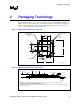
Packaging Technology R 2 Packaging Technology The 955X Express chipset consists of two individual components: the MCH and the ICH7. The MCH component uses a 34 mm squared, 6-layer flip chip ball grid array (FC-BGA) package (see Figure 2-1 through Figure 2-3). For information on the ICH7 package, refer to the Intel® I/O Controller Hub 7 (ICH7) Thermal Design Guidelines. Figure 2-1. MCH Package Dimensions (Top View) Ø5.20mm CapacitorArea, HandlingExclusion Zone Die Keepout Area 3.1 2.30 19.38 10.67 2.
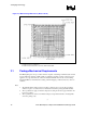
Packaging Technology R Figure 2-3. MCH Package Dimensions (Bottom View) NOTES: 1. All dimensions are in millimeters. 2. All dimensions and tolerances conform to ANSI Y14.5M-1994. 2.1 Package Mechanical Requirements The MCH package has an exposed bare die that is capable of sustaining a maximum static normal load of 10-lbf. The package is NOT capable of sustaining a dynamic or static compressive load applied to any edge of the bare die.
Thermal Specifications R 3 Thermal Specifications 3.1 Thermal Design Power (TDP) Analysis indicates that real applications are unlikely to cause the chipset MCH to consume maximum power dissipation for sustained time periods. Therefore, to arrive at a more realistic power level for thermal design purposes, Intel characterizes power consumption based on known platform benchmark applications. The resulting power consumption is referred to as the Thermal Design Power (TDP).
Thermal Specifications R 12 Intel® 955X Express Chipset Thermal/Mechanical Design Guide
Thermal Simulation R 4 Thermal Simulation Intel provides thermal simulation models of the 955X Express chipset MCH and associated user's guides to aid system designers in simulating, analyzing, and optimizing their thermal solutions in an integrated, system-level environment. The models are for use with the commercially available Computational Fluid Dynamics (CFD)-based thermal analysis tool “FLOTHERM”* (version 5.1 or higher) by Flomerics, Inc.
Thermal Simulation R 14 Intel® 955X Express Chipset Thermal/Mechanical Design Guide
Thermal Metrology R 5 Thermal Metrology The system designer must make temperature measurements to accurately determine the thermal performance of the system. Intel has established guidelines for proper techniques to measure the MCH die temperatures. Section 5.1 provides guidelines on how to accurately measure the MCH die temperatures. The flowchart in Figure 5-1 offers useful guidelines for thermal performance and evaluation. 5.
Thermal Metrology R Figure 5-1. Thermal Solution Decision Flowchart Start Attach device to board using normal reflow process. Attach thermocouples using recommended metrology. Setup the system in the desired configuration. Run the Power program and monitor the device die temperature. Tdie > Specification? No End Heatsink Required Select Heatsink Yes Therm_Solution_Flow Figure 5-2. Zero Degree Angle Attach Methodology Figure 5-3.
Reference Thermal Solution R 6 Reference Thermal Solution Intel has developed a reference thermal solution designed to meet the cooling needs of the MCH under operating environments and specifications defined in this document. This chapter describes the overall requirements for the Plastic Wave Soldering Heatsink (PWSH) reference thermal solution including critical-to-function dimensions, operating environment, and validation criteria.
Reference Thermal Solution R Figure 6-1. Reference Heatsink Measured Thermal Performance versus Approach Velocity 6.3 Mechanical Design Envelope While each design may have unique mechanical volume and height restrictions or implementation requirements, the height, width, and depth constraints typically placed on the MCH thermal solution are shown in Figure 6-2.
Reference Thermal Solution R Figure 6-2. Heatsink Volumetric Envelope for the MCH 33.50mm Ramp Retainer FCBGA +Solder Balls 1.90mm HeatsinkBase T IM Die 2.50mm HeatsinkFin Motherboard 60.6mm 48.0mm 26.79mm Heatsink Fin 60.92mm 45.79mm 67.0mm 81.0mm TNB Max 2.2 mm Component Height No component this Area 135 O 47.
Reference Thermal Solution R 6.4 Board-Level Components Keep-out Dimensions The location of hole patterns and keep-out zones for the reference thermal solution are shown in Figure 6-3 and Figure 6-4. Figure 6-3. MCH Heatsink Board Component Keep-out 60.6mm 48.0mm 26.79mm Heatsink Fin 60.92mm 45.79mm 67.0mm 81.0mm TNB Max 2.2 mm Component Height No component this Area 135O 47.
Reference Thermal Solution R Figure 6-4. Retention Mechanism Component Keep-out Zones 4 x 8.76 mm 4 x 8.76mm 4 x 1.84mm 4 x 5.08mm Max 1.27mm Component Height NoComponents this Area 8 x Ø0.97 mm P lated Thru H ole 8 x Ø1.42 mm Trace Keepout RM_Component_KeepoutZones 6.5 Reference Heatsink Thermal Solution Assembly The reference thermal solution for the MCH is a passive extruded heatsink with thermal interface.
Reference Thermal Solution R Figure 6-5. Plastic Wave Soldering Heatsink Assembly 6.5.1 Heatsink Orientation To enhance the efficiency of the reference thermal solution, it is important for the designer to orient the fins properly with respect to the mean airflow direction. Simulation and experimental evidence have shown that the MCH heatsink thermal performance is enhanced when the fins are aligned with the mean airflow direction (see Figure 6-3). 6.5.
Reference Thermal Solution R Figure 6-6. Plastic Wave Soldering Heatsink Extrusion Profile NOTE: All dimensions are in millimeters, with dimensions in braces expressed in inches. 6.5.3 Mechanical Interface Material There is no mechanical interface material associated with this reference solution. 6.5.4 Thermal Interface Material A TIM provides improved conductivity between the die and heatsink. The reference thermal solution uses Honeywell PCM 45F, 0.25 mm (0.010 in.) thick, 15 mm x 15 mm (0.59 in.
Reference Thermal Solution R 6.5.4.1 Effect of Pressure on TIM Performance As mechanical pressure increases on the TIM, the thermal resistance of the TIM decreases. This phenomenon is due to the decrease of the bond line thickness (BLT). BLT is the final settled thickness of the thermal interface material after installation of heatsink. The effect of pressure on the thermal resistance of the Honeywell* PCM45F TIM is shown in Table 6-1.
Reference Thermal Solution R 6.6 Reliability Guidelines Each motherboard, heatsink and attach combination may vary the mechanical loading of the component. Based on the end user environment, the user should define the appropriate reliability test criteria and carefully evaluate the completed assembly prior to use in high volume. Some general recommendations are shown in Table 6-2. Table 6-2.
Reference Thermal Solution R 26 Intel® 955X Express Chipset Thermal/Mechanical Design Guide
Appendix A: Thermal Solution Component Suppliers R 7 Appendix A: Thermal Solution Component Suppliers This list is provided by Intel solely as a convenience to customers. Intel has not tested, designed or validated these products and does not warrant user suitability or performance in any way. Customers are solely responsible for determining the suitability and application of these products for their designs. Table 7-1.
Appendix A: Thermal Solution Component Suppliers R Part Solder-Down Anchor Intel Part Number C85376-001 Supplier (Part Number) Wieson Contact Information Rick Lin Deputy Manager/Project Sales Department Add.: 7F, No. 276, Section 1, Tatung Road, Hsichih City, Taipei Hsien, Taiwan Tel: 886-2-2647-1896 ext. 6342 Mobile: 886-955644008 Email: rick@wieson.com Website: www.wieson.com NOTE: The enabled components may not be currently available from all suppliers.
Appendix B: Mechanical Drawings R 8 Appendix B: Mechanical Drawings Table 8-1 lists the mechanical drawings included in this appendix. Table 8-1.
Appendix B: Mechanical Drawings R Figure 8-1.
Appendix B: Mechanical Drawings R Figure 8-2.
Appendix B: Mechanical Drawings R Figure 8-3.
Appendix B: Mechanical Drawings R Figure 8-4.
Appendix B: Mechanical Drawings R Figure 8-5.
Appendix B: Mechanical Drawings R Figure 8-6.
Appendix B: Mechanical Drawings R Figure 8-7.