LE-370/LE-370Z 3.5 Inches Embedded Miniboard User’s Manual Edition: 1.
LE-370 User’s Manual Copyright Copyright 2004 - 2005. All rights reserved. This document is copyrighted and all rights are reserved. The information in this document is subject to change without prior notice to make improvements to the products. This document contains proprietary information and protected by copyright. No part of this document may be reproduced, copied, or translated in any form or any means without prior written permission of the manufacturer.
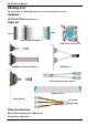
LE-370 User’s Manual Packing List: Please check the package before you starting setup the system Hardware: LE-370/LE-370Z motherboard x 1 Cable Kit: 44-pin 40-pin 44-pin 44-pin ATA33 IDE Cable x 1 CPU Cooler (LE-370 only) COM port & Printer Port Cable x 1 USB Cable x 1 PS/2 keyboard & mouse cable x 1 Floppy Cable x 1 Audio Cable x 1 1 to 3 power output cable Other Accessories: Divers CD (including User’s Manual) x 1 Printed User’s Manual x 1 Packing List 3
LE-370 User’s Manual Index Chapter 1 .................................................................................. 7 1.1 .............................................................................. 7 1.2 ........................................................................ 8 1.3 ........................................................................ 10 1.4 .................................................
LE-370 User’s Manual 2.13 ......................................................................... 31 Chapter 3 ............................................................................. 33 3.1 ...................................................................... 33 Chapter 4 ................................................................................. 35 Appendix A ....................................
LE-370 User’s Manual (This Page is Left For Blank) 6
LE-370 User’s Manual Introduction Chapter 1 1.1 LE-370/LE-370Z are the 3.5 inches embedded miniboards based on Intel 852GME/GM of platform, with Intel Pentium M/Celeron M processors supported, onboard VGA, LAN, Audio, USB2.0, CF, LVDS, and mini-PCI to meet the variable applications of users. LE-370Z with onboard Intel Celeron M processor for ultra low power can offer the fanless solution for such as medical applications.
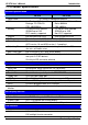
LE-370 User’s Manual Introduction 1.2 General Specification LE-370 Form Factor CPU Memory Chipset BIOS Green Function Watchdog Timer Real Time Clock Enhanced IDE LE-370Z 3.
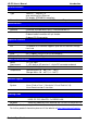
LE-370 User’s Manual Introduction Ethernet Interface Controller Type Connector Intel 82562ET PHY 10Base-T / 100Base-TX auto-switching Fast Ethernet Full duplex, IEEE802.
LE-370 User’s Manual Introduction 1.
LE-370 User’s Manual Introduction 1.4 Intel Pentium M processor with FC-PGA2/FC-BGA2 CRT/LCD Monitor LVDS 1 x 184-pin DDR DIMM up to 1GB 852GME/GM 2 x USB2.
LE-370 User’s Manual (This Page is Left for Blank) 12
LE-370 User’s Manual Hardware Setup Chapter 2 2.
LE-370 User’s Manual Hardware Setup 2.
LE-370 User’s Manual Hardware Setup 2.3 2.3.
LE-370 User’s Manual Hardware Setup 2.4 2.4.1 LE-370 supports onboard socket479 for Intel Pentium M/Celeron M processors with FC-PGA478 package, 400/533MHz of front side bus; LE-370Z integrates onboard Intel Celeron M 600MHz processor with 400MHz of front side bus. For LE-370 please follow the instruction to install the CPU properly. CPU Socket 1. Use flat-type Screw Driver to 2. Find the pin direction and unlock the CPU locket install the processor on the socket.
LE-370 User’s Manual Hardware Setup 2.4.2 LE-370 supports DDR266/333 up to 1GB with ECC; LE-370Z supports DDR200/266 up to 1GB with unbuffered, non-ECC memory module. DIMM 104-pin 80-pin Please check the pin number to match the socket side well before installing memory module.
LE-370 User’s Manual Hardware Setup 2.4.3 The LE-370 provides one CPU cooler; please follow the instruction below to finish the installation. The LE-370Z comes with a heat sink on embedded processor, no fan is required. 1. Install CPU properly 2. Put the cooler on the socket 3. Press the clips into the through hole 4.
LE-370 User’s Manual Hardware Setup 2.5 The board’s data of CMOS can be setting in BIOS. If the board refuses to boot due to inappropriate CMOS settings, here is how to proceed to clear (reset) the CMOS to its default values.
LE-370 User’s Manual Hardware Setup 2.6 The board supports one UltraDMA133 IDE interface, and one CompactFlash Type 1 socket with secondary IDE mode, the 44-pin IDE1 connector can support up to 2 ATAPI devices through IDE cable.
LE-370 User’s Manual Hardware Setup 2.7 The board provides a slim type floppy port; please use the 26-pin ribbon cable in the package to connect the floppy device. FDD 1. Floppy rear side Floppy Port Lift up the brown plastic bar 2. Slot the cable in (Blue paste for 3. brown bar side) Press back the plastic bar 4. Lift up this plastic bar 5. Slot the cable in (Blue paste for outside) 6.
LE-370 User’s Manual Hardware Setup 2.8 The board integrates Ethernet controller with Intel 82562ET PHY, full compliance with IEEE 802.3u 100Base-T specifications and IEEE 802.3x Full Duplex Flow Control, the board supports Wake-Up-On-LAN by BIOS configurable.
LE-370 User’s Manual Hardware Setup 2.9 Based on Intel 852GME/GM chipset with built-in Intel Extreme Graphics, the board provides onboard VGA display interface, and one 18/24-bit LVDS LCD interface, supports up to 1600 x 1200 of resolution for LE-370 (with 852GME) and 1400 x 1050 for LE-370Z (with 852GM). The two display interfaces can be set for dual display with extended desktop mode or clone mode.
LE-370 User’s Manual Hardware Setup 2.9.2 The onboard digital display interface comes with a 40-pin header connector to provide 18/24-bit LVDS LCD interface, and one backlight inverter connector for powering and enable/disable control, the jumper JVLCD is to set the panel voltage.
LE-370 User’s Manual Hardware Setup Connector: CN_INV Type: 5-pin LVDS Power Header Pin 1 2 3 Description +12V GND GND 4 5 Connector: JVLCD Type: 3-pin Power select Header Pin 1 2 3 Description VCC LCDVCC VCC3 GND ENABKL Connector: CN_LVDS Type: onboard 40-pin connector for LVDS connector Connector model: HIROSE DF13-40DP-1.
LE-370 User’s Manual Hardware Setup To setup the LCD, you need the component below: 1. A panel with LVDS interfaces. 2. An inverter for panel’s backlight power. 3. A LCD cable and an inverter cable. For the cables, please follow the pin assignment of the connector to make a cable, because every panel has its own pin assignment, so we do not provide a standard cable; please find a local cable manufacture to make cables. LCD Installation Guide: 1.
LE-370 User’s Manual Hardware Setup After setup the devices well, you need to select the LCD panel type in the BIOS. The panel type mapping is list below: BIOS panel type selection form For 18-bit color For 24-bit color NO. Output format NO.
LE-370 User’s Manual Hardware Setup 2.10 The board integrates onboard AC97 audio with REALTEK ALC201A, supports 18-bit ADC and DAC resolution, and Line-out, Line-in and MIC-in input/output interfaces. Connector: CN_AUDIO Type: 10-pin (2 x 5) 1.27mm x 2.54mm-pitch header Pin Description Pin Description 1 Line – Left 2 Ground 3 Line – Right 4 MIC1 5 MIC2 6 Ground 7 N/C 8 Line Out – Left 9 Line Out – Right 10 Ground Connector: CDIN Type: 4-pin header (pitch = 2.
LE-370 User’s Manual Hardware Setup 2.11 The board offers 8-bit digital I/O to customize its configuration to your control needs. For example, you may configure the digital I/O to control the opening and closing of the cash drawer or to sense the warning signal from a tripped UPS. Connector: CN_DIO Type: onboard 2 x 6-pin 1.27mm x 2.
LE-370 User’s Manual Hardware Setup 2.12 2.12.1 The board requires DC 12V input with onboard DC jack or 4-pin 12V DC connector. Connector: CN_12V Type: 4-pin standard ATX2.0 +12V power connector Pin Description Pin Description 1 Ground 2 Ground 3 +12V 4 +12V 2.12.2 The board also provides one 4-pin connector with +5V/+12V output.
LE-370 User’s Manual Hardware Setup 2.13 The JFRNT provides front control panel of the board, such as power button, reset and beeper, etc. Please check well before you connecting the cables on the chassis. Connector: JFRNT Type: onboard 14-pin (2 x 7) 2.
LE-370 User’s Manual (This Page is Left for Blank) 32
LE-370 User’s Manual System Setup Chapter 3 3.1 The board provides onboard VGA with DB15 analog display interface, and LVDS LCD interface for digital display, when connecting two display devices, you can enable dual display function with clone mode or extended desktop mode. Before setup the video setting, please install the VGA driver well.
LE-370 User’s Manual System Setup Please select Devices for advanced device setting. Single Display Device Setting Dual Display Device Setting When you set dual display clone mode, you’ll see the same screen display on two devices. When you set the dual display for extended desktop mode, you can have the independent desktop on the second device.
LE-370 User’s Manual BIOS Setup Chapter 4 The single board computer uses the Award BIOS for the system configuration. The Award BIOS in the single board computer is a customized version of the industrial standard BIOS for IBM PC AT-compatible computers. It supports Intel x86 and compatible CPU architecture based processors and computers. The BIOS provides critical low-level support for the system central processing, memory and I/O sub-systems.
LE-370 User’s Manual (This Page is Left for Blank) 36
LE-370 User’s Manual I/O Port Pin Assignment Appendix A A.
LE-370 User’s Manual I/O Port Pin Assignment A.2 Connector: FDD Type: 26-pin connector Pin Description 1 VCC 3 VCC 5 VCC 7 DRV1 9 MTR1 11 RPM 13 N/C 15 Ground 17 Ground 19 N/C 21 N/C 23 Ground 25 Ground Pin 2 4 6 8 10 12 14 16 18 20 22 24 26 Description INDEX DRV0 DSKCHG N/C MTR0 DIR STEP WRITE DATA WRITE GATE TRACK 0 WRPTR RDATASEL A.3 5 Connector: CN_IR Type: 5-pin header for SIR Ports Pin Description 1 VCC 2 N/C 3 IRRX 4 Ground 5 IRTX 6 A.
LE-370 User’s Manual I/O Port Pin Assignment A.5 Connector: COM1 Type: 9-pin D-sub male connector on bracket Pin Description Pin 1 DCD 6 2 RXD 7 3 TXD 8 4 DTR 9 5 Ground 1 2 3 4 5 6 7 8 9 Description DSR RTS CTS -XR 1 2 9 10 Connector: CN_COM2 Type: 10-pin (2 x 5) 1.27mm x 2.54mm-pitch header Pin Description Pin Description 1 DCD 2 3 RXD 4 RTS 5 TXD 6 CTS 7 DTR 8 -XR 9 Ground 10 A.
LE-370 User’s Manual I/O Port Pin Assignment A.8 < LPT Port > 14 Connector: CN_LPT Type: 26-pin (13 x 2) header for LPT Ports Pin 1 3 5 7 9 11 13 15 17 19 21 23 25 Description PSTBPRO1 PRO3 PRO5 PRO7 BUSY SLCT ERRSLINGround Ground Ground Ground Pin 2 4 6 8 10 12 14 16 18 20 22 24 26 26 1 13 Description PRO0 PRO2 PRO4 PRO6 ACKPE AFDINTGround I/O Ground Ground Ground N/C A.
LE-370 User’s Manual I/O Port Pin Assignment (This Page is Left for Blank) Serial Port 41
LE-370 User’s Manual Flash BIOS Appendix B B.1 BIOS Auto Flash Tool The board is based on Award BIOS and can be updated easily by the BIOS auto flash tool. You can download the tool online at the address below: http://www.award.com http://www.commell.com.tw/support/support.htm File name of the tool is “awdflash.exe”, it’s the utility that can write the data into the BIOS flash ship and update the BIOS. B.2 Flash Method 1. Please make a bootable floppy disk. 2. Get the last .
LE-370 User’s Manual Flash BIOS (This Page is Left for Blank) Flash BIOS 43
LE-370 User’s Manual Hardware Test Appendix C C.1 Hardware Board CPU Memory HDD CDROM Power Supply LE-370Z Intel® Celeron® M 600MHz Infineon DDR333 512MB x1 Hitachi IC25N080ATMR04 80GB SDR-038 4x DVD-ROM SEVENTEAM ST-402HLP (not counted) Software OS Application Windows XP SP1 English Version 3DMARK 2003 Test Result Without LCD panel With 10.4” LCD panel With 15” LCD panel With 17” LCD panel 44 24W 30W 38.
LE-370 User’s Manual Contact Information Contact Information Any advice or comment about our products and service, or anything we can help you please don’t hesitate to contact with us. We will do our best to support you for your project and business. Taiwan Commate Computer Inc. Address 8F, No. 94, Sec. 1, Shin Tai Wu Rd., Shi Chih Taipei Hsien, Taiwan TEL +886-2-26963909 FAX +886-2-26963911 Website http://www.commell.com.tw E-Mail info@commell.com.tw (General Information) tech@commell.com.