
User's Manual
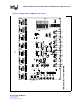
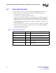
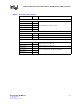
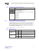
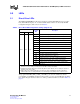
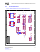
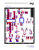
Table Of Contents
- 1.0 General Description
- 2.0 Introduction
- 3.0 Quick-Start Checklist
- 4.0 Optional Configurations
- 5.0 LEDs
- 6.0 Board Schematics
- Figure 4. LXD9785 PQFP MII Demo Board Power (Fiber Board Revision A2)
- Figure 5. Control
- Figure 6. MII Ports 0 and 1
- Figure 7. MII Ports 2 and 3
- Figure 8. MII Ports 4 and 5
- Figure 9. MII Ports 6 and 7
- Figure 10. Fiber Ports 0 and 1
- Figure 11. Fiber Ports 2 and 3
- Figure 12. Fiber Ports 4 and 5
- Figure 13. Fiber Ports 6 and 7
- Figure 14. Caps
- Figure 15. SS-SMII to MII ALTERA
- Figure 16. Clock Distribution
- Figure 17. Inter-Frame Status LEDs
- Figure 18. Logic Analyzer
- Figure 19. MDIO0 and MDC0 Fix
- Figure 20. MDIO1 and MDC1 Fix
- 7.0 Bill of Materials
LXD9785 PQFP Demo Board with FPGA for SS-SMII (Fiber)-to-MII Conversion
18 Development Kit Manual
Document #: 249323
Revision #: 003
Rev. Date: January 24, 2002
5.2 Inter Frame Status LEDs
By using the conversion FPGAs, the Inter Frame Status information for Speed status, Duplex
status, and Link status are output to an LED circuit. The LEDs (D101 - D154) provide a
continuous, real-time status for all eight ports. This feature is provided to assist the customer in
evaluation of the Inter Frame Status operation.
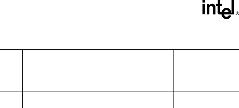
Table 9. LED Pulse Stretch Settings (Register 20)
Bit Name Description Type Default
20.3:2 LEDFREQ
00 = Stretch LED events to 30 ms.
01 = Stretch LED events to 60 ms.
10 = Stretch LED events to 100 ms.
11 = Reserved.
R/W 00
20.1
PULSE-
STRETCH
0 = Disable pulse stretching of all LEDs.
1 = Enable pulse stretching of all LEDs.
R/W 1