
Solid-State Drive 520 Series
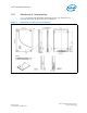
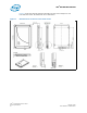
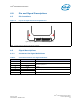
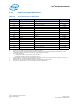
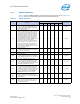
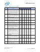

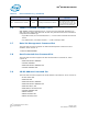
Table Of Contents
- Intel® Solid-State Drive 520 Series
- Contents
- 1.0 Overview
- 2.0 Product Specifications
- 3.0 Mechanical Information
- 4.0 Pin and Signal Descriptions
- 5.0 Supported Command Sets
- 5.1 ATA General Feature Command Set
- 5.2 Power Management
- 5.3 Security Mode Feature Set
- 5.4 SMART Command Set
- 5.5 Device Statistics
- 5.6 SMART Command Transport (SCT)
- 5.7 Data Set Management Command Set
- 5.8 Host Protected Area Command Set
- 5.9 48-Bit Address Command Set
- 5.10 General Purpose Log Command Set
- 5.11 Native Command Queuing
- 5.12 Software Settings Preservation
- 5.13 SATA Link Power Management (LPM)
- 6.0 Certifications and Declarations
- 7.0 References
- 8.0 Terms and Acronyms
- 9.0 Revision History
- Appendix A IDENTIFY DEVICE Command Data
Intel
®
Solid-State Drive 520 Series
February 2012 Product Specification
Order Number: 325968-001US 13
Intel
®
Solid-State Drive 520 Series
4.0 Pin and Signal Descriptions
4.1 Pin Locations
Note: 2.5-inch connector supports in-built latching capability.
4.2 Signal Descriptions
4.2.1 Connector Pin Signal Definitions
Note: Key and spacing separate signal and power segments.
Figure 3. Layout of Signal and Power Segment Pins
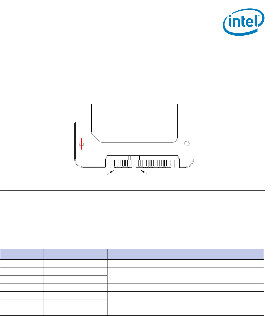
Table 9. Serial ATA Connector Pin Signal Definitions
Pin Function Definition
S1 Ground 1st mate
S2 A+
Differential signal pair A
S3 A-
S4 Ground 1st mate
S5 B-
Differential signal pair B
S6 B+
S7 Ground 1st mate
Signal Segment S1 Power Segment P1