Intel® Xeon® Processor E3-1200 v3 Product Family Datasheet – Volume 1 of 2 June 2013 Order No.
INFORMATION IN THIS DOCUMENT IS PROVIDED IN CONNECTION WITH INTEL PRODUCTS. NO LICENSE, EXPRESS OR IMPLIED, BY ESTOPPEL OR OTHERWISE, TO ANY INTELLECTUAL PROPERTY RIGHTS IS GRANTED BY THIS DOCUMENT.
Contents—Processor Contents Revision History..................................................................................................................8 1.0 Introduction................................................................................................................. 9 1.1 1.2 1.3 1.4 1.5 1.6 1.7 Supported Technologies.........................................................................................10 Interfaces..................................................................
Processor—Contents 4.2 Processor Core Power Management......................................................................... 50 4.2.1 Enhanced Intel® SpeedStep® Technology Key Features..................................50 4.2.2 Low-Power Idle States............................................................................... 51 4.2.3 Requesting Low-Power Idle States...............................................................52 4.2.4 Core C-State Rules.................................................
Contents—Processor 6.14 Processor Internal Pull-Up / Pull-Down Terminations................................................ 85 7.0 Electrical Specifications.............................................................................................. 86 7.1 7.2 7.3 7.4 7.5 7.6 7.7 7.8 Integrated Voltage Regulator..................................................................................86 Power and Ground Lands ......................................................................................
Processor—Contents Tables 1 2 3 4 5 6 7 8 9 10 11 12 13 14 15 16 17 18 19 20 21 22 23 24 25 26 27 28 29 30 31 32 33 34 35 36 37 38 39 40 41 42 43 44 45 46 47 48 49 50 51 52 Terminology........................................................................................................... 12 Related Documents..................................................................................................15 Processor DIMM Support by Product................................................................
Contents—Processor 53 54 Processor Storage Specifications.............................................................................. 104 Processor Ball List by Signal Name........................................................................... 106 June 2013 Order No.
Processor—Revision History Revision History Revision 001 Description • Initial Release Intel® Xeon® Processor E3-1200 v3 Product Family Datasheet – Volume 1 of 2 8 Date June 2013 June 2013 Order No.
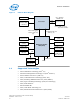
Introduction—Processor 1.0 Introduction The Intel® Xeon® processor E3-1200 v3 product family are 64-bit, multi-core processors built on 22-nanometer process technology. The processors are designed for a two-chip platform consisting of a processor and Platform Controller Hub (PCH). The processors are designed to be used with the Intel® C220 Series chipset. See the following figure for an example platform block diagram.
Processor—Introduction Figure 1. Platform Block Diagram 1333 / 1600 MT/s 2 DIMMs / CH PCI Express* 3.0 CH A Processor Digital Display Interface (DDI) (3 interfaces) System Memory CH B Note: 2 DIMMs / CH is not supported on all SKUs. Intel® Flexible Display Interface (Intel® FDI) (x2) Direct Media Interface 2.0 (DMI 2.0) (x4) USB 3.0 (up to 6 Ports) Analog Display (VGA) USB 2.0 (8 Ports) Integrated LAN Platform Controller Hub (PCH) SATA, 6 GB/s (up to 6 Ports) SPI Flash PCI Express* 2.
Introduction—Processor • Intel® Advanced Encryption Standard New Instructions (Intel® AES-NI) • PCLMULQDQ Instruction • Intel® Secure Key • Intel® Transactional Synchronization Extensions (Intel® TSX) • PAIR – Power Aware Interrupt Routing • SMEP – Supervisor Mode Execution Protection Note: The availability of the features may vary between processor SKUs. 1.2 Interfaces The processor supports the following interfaces: 1.
Processor—Introduction 1.4 1.5 Thermal Management Support • Digital Thermal Sensor • Adaptive Thermal Monitor • THERMTRIP# and PROCHOT# support • On-Demand Mode • Memory Open and Closed Loop Throttling • Memory Thermal Throttling • External Thermal Sensor (TS-on-DIMM and TS-on-Board) • Render Thermal Throttling • Fan speed control with DTS Package Support The processor socket type is noted as LGA 1150. The package is a 37.5 x 37.5 mm Flip Chip Land Grid Array (FCLGA 1150).
Introduction—Processor Term Description eDP Embedded Display Port EPG Electrical Power Gating EU Execution Unit FMA Floating-point fused Multiply Add instructions FSC Fan Speed Control HDCP High-bandwidth Digital Content Protection HDMI* High Definition Multimedia Interface HFM High Frequency Mode iDCT Inverse Discrete IHS Integrated Heat Spreader GFX Graphics GUI Graphical User Interface IMC Integrated Memory Controller Intel® 64 Technology 64-bit memory extensions to the IA-3
Processor—Introduction Term Description NCTF Non-Critical to Function. NCTF locations are typically redundant ground or non-critical reserved, so the loss of the solder joint continuity at end of life conditions will not affect the overall product functionality. ODT On-Die Termination OLTM Open Loop Thermal Management PCG Platform Compatibility Guide (PCG) (previously known as FMB) provides a design target for meeting all planned processor frequency requirements. PCH Platform Controller Hub.
Introduction—Processor Term Description TCONTROL TCONTROL is a static value that is below the TCC activation temperature and used as a trigger point for fan speed control. When DTS > TCONTROL, the processor must comply to the TTV thermal profile. TDP Thermal Design Power: Thermal solution should be designed to dissipate this target power level. TDP is not the maximum power that the processor can dissipate. TLB Translation Look-aside Buffer TTV Thermal Test Vehicle.
Processor—Introduction Document Document Number / Location Advanced Configuration and Power Interface 3.0 http:// www.acpi.info/ PCI Local Bus Specification 3.0 http:// www.pcisig.com/ specifications PCI Express Base Specification, Revision 2.0 http:// www.pcisig.com DDR3 SDRAM Specification http:// www.jedec.org DisplayPort* Specification http://www.vesa.org Intel® 64 and IA-32 Architectures Software Developer's Manuals http:// www.intel.com/ products/processor/ manuals/index.
Interfaces—Processor 2.0 Interfaces 2.1 System Memory Interface • Two channels of DDR3/DDR3L Unbuffered Dual In-Line Memory Modules (UDIMM) with a maximum of two DIMMs per channel. • Single-channel and dual-channel memory organization modes • Data burst length of eight for all memory organization modes • Memory data transfer rates of 1333 MT/s and 1600 MT/s • 64-bit wide channels • DDR3/DDR3L I/O Voltage of 1.5 V for Intel AMT Server, and Workstation • DDR3L I/O voltage of 1.
Processor—Interfaces 2.1.1 System Memory Technology Supported The Integrated Memory Controller (IMC) supports DDR3/DDR3L protocols with two independent, 64-bit wide channels each accessing one or two DIMMs. The type of memory supported by the processor is dependent on the PCH SKU in the target platform. Note: The IMC supports a maximum of two DDR3/DDR3L DIMMs per channel; thus, allowing up to four device ranks per channel.
Interfaces—Processor Raw Card Version DIMM Capacity DRAM Device Technology DRAM Organization # of DRAM Devices # of Physical Devices Ranks # of Row / Col Address Bits # of Banks Inside DRAM Page Size A 1 GB 1 Gb 128 M X 8 8 1 14/10 8 8K 2 GB 1 Gb 128 M X 8 16 2 14/10 8 8K 4 GB 2 Gb 256 M X 8 16 2 15/10 8 8K 4 GB 4 Gb 512 M X 8 8 1 15/10 8 8K 8 GB 4 Gb 512 M X 8 16 2 16/10 8 8K B Server and Workstation Platforms Unbuffered / ECC Supported DIMM Module Config
Processor—Interfaces Dual-Channel Mode – Intel® Flex Memory Technology Mode The IMC supports Intel Flex Memory Technology Mode. Memory is divided into symmetric and asymmetric zones. The symmetric zone starts at the lowest address in each channel and is contiguous until the asymmetric zone begins or until the top address of the channel with the smaller capacity is reached.
Interfaces—Processor 2.1.3.1 System Memory Frequency In all modes, the frequency of system memory is the lowest frequency of all memory modules placed in the system, as determined through the SPD registers on the memory modules. The system memory controller supports one or two DIMM connectors per channel. The usage of DIMM modules with different latencies is allowed, but in that case, the worst latency (among two channels) will be used.
Processor—Interfaces 2.2 PCI Express* Interface This section describes the PCI Express* interface capabilities of the processor. See the PCI Express Base* Specification 3.0 for details on PCI Express*. 2.2.1 PCI Express* Support The PCI Express* lanes (PEG[15:0] TX and RX) are fully-compliant to the PCI Express Base Specification, Revision 3.0. The Intel® Xeon® processor with the Server / Workstation PCH supports the configurations shown in the following table (may vary depending on PCH SKUs). Table 5.
Interfaces—Processor • Traditional AGP style traffic (asynchronous non-snooped, PCI-X Relaxed ordering). • Peer segment destination posted write traffic (no peer-to-peer read traffic) in Virtual Channel 0: DMI -> PCI Express* Port 0 • 64-bit downstream address format, but the processor never generates an address above 64 GB (Bits 63:36 will always be zeros).
Processor—Interfaces Figure 3. PCI Express* Related Register Structures in the Processor PCI Express* Device PEG0 PCI-PCI Bridge representing root PCI Express ports (Device 1 and Device 6) PCI Compatible Host Bridge Device (Device 0) DMI PCI Express* extends the configuration space to 4096 bytes per-device/function, as compared to 256 bytes allowed by the conventional PCI specification.
Interfaces—Processor Figure 4. PCI Express* Typical Operation 16 Lanes Mapping 0 1 2 3 4 0 2.3 6 7 8 9 2 10 3 11 4 12 5 13 2 6 14 3 7 15 0 1 1 X 8 Controller 1 X 4 Controller 1 1 X 16 Controller 5 Lane 0 Lane 1 Lane 2 Lane 3 Lane 4 Lane 5 Lane 6 Lane 7 Lane 8 Lane 9 Lane 10 Lane 11 Lane 12 Lane 13 Lane 14 Lane 15 0 1 2 3 4 5 6 7 8 9 10 11 12 13 14 15 Direct Media Interface (DMI) Direct Media Interface (DMI) connects the processor and the PCH. Next generation DMI2 is supported.
Processor—Interfaces • 5 GT/s point-to-point DMI interface to PCH is supported. • Raw bit-rate on the data pins of 5.0 GB/s, resulting in a real bandwidth per pair of 500 MB/s given the 8b/10b encoding used to transmit data across this interface. Does not account for packet overhead and link maintenance. • Maximum theoretical bandwidth on interface of 2 GB/s in each direction simultaneously, for an aggregate of 4 GB/s when DMI x4. • Shares 100-MHz PCI Express* reference clock.
Interfaces—Processor 2.4 Processor Graphics The processor graphics contains a generation 7.5 graphics core architecture. This enables substantial gains in performance and lower power consumption over previous generations. Up to 20 Execution Units are supported depending on the processor SKU.
Processor—Interfaces Figure 5. Processor Graphics Controller Unit Block Diagram 2.5.1 3D and Video Engines for Graphics Processing The Gen 7.5 3D engine provides the following performance and power-management enhancements. 3D Pipeline The 3D graphics pipeline architecture simultaneously operates on different primitives or on different portions of the same primitive. All the cores are fully programmable, increasing the versatility of the 3D Engine. 3D Engine Execution Units • Supports up to 20 EUs.
Interfaces—Processor Vertex Shader (VS) Stage The VS stage performs shading of vertices output by the VF function. The VS unit produces an output vertex reference for every input vertex reference received from the VF unit, in the order received. Geometry Shader (GS) Stage The GS stage receives inputs from the VS stage. Compiled application-provided GS programs, specifying an algorithm to convert the vertices of an input object into some output primitives.
Processor—Interfaces Logical 128-Bit Fixed BLT and 256 Fill Engine This BLT engine accelerates the GUI of Microsoft Windows* operating systems. The 128-bit BLT engine provides hardware acceleration of block transfers of pixel data for many common Windows operations.
Interfaces—Processor The HDMI* interface supports HDMI with 3D, 4K, Deep Color, and x.v.Color. The DisplayPort* interface supports the VESA DisplayPort* Standard Version 1, Revision 2. • The processor supports High-bandwidth Digital Content Protection (HDCP) for high-definition content playback over digital interfaces. • The processor also integrates dedicated a Mini HD audio controller to drive audio on integrated digital display interfaces, such as HDMI* and DisplayPort*.
Processor—Interfaces • Organizing pixels into frames • Optionally scaling the image to the desired size • Re-timing data for the intended target • Formatting data according to the port output standard DisplayPort* DisplayPort* is a digital communication interface that uses differential signaling to achieve a high-bandwidth bus interface designed to support connections between PCs and monitors, projectors, and TV displays.
Interfaces—Processor TMDS data and clock channels. These channels are used to carry video, audio, and auxiliary data. In addition, HDMI carries a VESA DDC. The DDC is used by an HDMI Source to determine the capabilities and characteristics of the Sink. Audio, video, and auxiliary (control/status) data is transmitted across the three TMDS data channels. The video pixel clock is transmitted on the TMDS clock channel and is used by the receiver for data recovery on the three data channels.
Processor—Interfaces Embedded DisplayPort* Embedded DisplayPort* (eDP*) is an embedded version of the DisplayPort standard oriented towards applications such as notebook and All-In-One PCs. Digital Port D can be configured as eDP. Like DisplayPort, Embedded DisplayPort also consists of a Main Link, Auxiliary channel, and an optional Hot-Plug Detect signal. The eDP on the processor can be configured for 2 or 4 lanes. The processor supports Embedded DisplayPort* (eDP*) Standard Version 1.
Interfaces—Processor Table 7.
Processor—Interfaces 2.7 2.8 Intel® Flexible Display Interface (Intel® FDI) • The Intel Flexible Display Interface (Intel FDI) passes display data from the processor (source) to the PCH (sink) for display through a display interface on the PCH. • Intel FDI supports 2 lanes at 2.7 GT/s fixed frequency. This can be configured to 1 or 2 lanes depending on the bandwidth requirements. • Intel FDI supports 8 bits per color only. • Side band sync pin (FDI_CSYNC). • Side band interrupt pin (DISP_INT).
Interfaces—Processor Figure 9. Example for PECI Host-Clients Connection VTT VTT Q3 nX Q1 nX PECI Q2 1X CPECI <10pF/Node Host / Originator PECI Client Additional PECI Clients June 2013 Order No.
Processor—Technologies 3.0 Technologies This chapter provides a high-level description of Intel technologies implemented in the processor. The implementation of the features may vary between the processor SKUs. Details on the different technologies of Intel processors and other relevant external notes are located at the Intel technology web site: http://www.intel.com/technology/ 3.
Technologies—Processor • More reliable: Due to the hardware support, VMMs can now be smaller, less complex, and more efficient. This improves reliability and availability and reduces the potential for software conflicts. • More secure: The use of hardware transitions in the VMM strengthens the isolation of VMs and further prevents corruption of one VM from affecting others on the same system.
Processor—Technologies • Descriptor-Table Exiting — Descriptor-table exiting allows a VMM to protect a guest OS from internal (malicious software based) attack by preventing relocation of key system data structures like IDT (interrupt descriptor table), GDT (global descriptor table), LDT (local descriptor table), and TSS (task segment selector). — A VMM using this feature can intercept (by a VM exit) attempts to relocate these data structures and prevent them from being tampered by malicious software.
Technologies—Processor Figure 10.
Processor—Technologies • Memory controller and processor graphics comply with the Intel VT-d 1.2 Specification. • Two Intel VT-d DMA remap engines.
Technologies—Processor Another aspect of the trust decision is the ability of the platform to resist attempts to change the controlling environment. The Intel TXT platform will resist attempts by software processes to change the controlling environment or bypass the bounds set by the controlling environment.
Processor—Technologies Intel recommends enabling Intel HT Technology with Microsoft Windows* 8 and Microsoft Windows* 7 and disabling Intel HT Technology using the BIOS for all previous versions of Windows* operating systems. For more information on Intel HT Technology, see http://www.intel.com/technology/platform-technology/hyperthreading/. 3.
Technologies—Processor digital signal processing software. FMA improves performance in face detection, professional imaging, and high performance computing. Gather operations increase vectorization opportunities for many applications. In addition to the vector extensions, this generation of Intel processors adds new bit manipulation instructions useful in compression, encryption, and general purpose software. For more information on Intel AVX, see http://www.intel.com/software/avx 3.
Processor—Technologies performance of fine-grain locking while actually programming using coarse-grain locks. Details on Intel TSX may be found in Intel® Architecture Instruction Set Extensions Programming Reference. 3.8 Intel® 64 Architecture x2APIC The x2APIC architecture extends the xAPIC architecture that provides key mechanisms for interrupt delivery. This extension is primarily intended to increase processor addressability.
Technologies—Processor Note: • The semantics for accessing APIC registers have been revised to simplify the programming of frequently-used APIC registers by system software. Specifically, the software semantics for using the Interrupt Command Register (ICR) and End Of Interrupt (EOI) registers have been modified to allow for more efficient delivery and dispatching of interrupts. • The x2APIC extensions are made available to system software by enabling the local x2APIC unit in the “x2APIC” mode.
Processor—Power Management 4.0 Power Management This chapter provides information on the following power management topics: Figure 11.
Power Management—Processor 4.1 Advanced Configuration and Power Interface (ACPI) States Supported This section describes the ACPI states supported by the processor. Table 9. System States State G0/S0 G1/S3-Cold Full On Mode. Suspend-to-RAM (STR). Context saved to memory (S3-Hot state is not supported by the processor). G1/S4 Suspend-to-Disk (STD). All power lost (except wakeup on PCH). G2/S5 Soft off. All power lost (except wakeup on PCH). Total reboot. G3 Table 10. Description Mechanical off.
Processor—Power Management Table 13. Direct Media Interface (DMI) States State Table 14. Table 15. 4.2 Description L0 Full on – Active transfer state. L0s First Active Power Management low power state – Low exit latency. L1 Lowest Active Power Management – Longer exit latency. L3 Lowest power state (power-off) – Longest exit latency.
Power Management—Processor 4.2.2 • Multiple frequency and voltage points for optimal performance and power efficiency. These operating points are known as P-states. • Frequency selection is software controlled by writing to processor MSRs. The voltage is optimized based on the selected frequency and the number of active processor cores. — Once the voltage is established, the PLL locks on to the target frequency. — All active processor cores share the same frequency and voltage.
Processor—Power Management Figure 13. Thread and Core C-State Entry and Exit C0 MWAIT(C1), HLT MWAIT(C1), HLT (C1E Enabled) C1 C1E MWAIT(C7), P_LVL4 I/O Read MWAIT(C3), P_LVL2 I/O Read MWAIT(C6), P_LVL3 I/O Read C3 C6 C7 While individual threads can request low power C-states, power saving actions only take place once the core C-state is resolved. Core C-states are automatically resolved by the processor.
Power Management—Processor Note: When P_LVLx I/O instructions are used, MWAIT sub-states cannot be defined. The MWAIT sub-state is always zero if I/O MWAIT redirection is used. By default, P_LVLx I/O redirections enable the MWAIT 'break on EFLAGS.IF’ feature that triggers a wakeup on an interrupt, even if interrupts are masked by EFLAGS.IF. 4.2.
Processor—Power Management Core C6 State Individual threads of a core can enter the C6 state by initiating a P_LVL3 I/O read or an MWAIT(C6) instruction. Before entering core C6 state, the core will save its architectural state to a dedicated SRAM. Once complete, a core will have its voltage reduced to zero volts. During exit, the core is powered on and its architectural state is restored.
Power Management—Processor — For package C-states, the processor is not required to enter C0 state before entering any other C-state. — Entry into a package C-state may be subject to auto-demotion – that is, the processor may keep the package in a deeper package C-state than requested by the operating system if the processor determines, using heuristics, that the deeper C-state results in better power/performance. The processor exits a package C-state when a break event is detected.
Processor—Power Management Figure 14. Package C-State Entry and Exit C0 C3 C6 C1 C7 Package C0 State This is the normal operating state for the processor. The processor remains in the normal state when at least one of its cores is in the C0 or C1 state or when the platform has not granted permission to the processor to go into a low power state. Individual cores may be in lower power idle states while the package is in C0 state.
Power Management—Processor Package C2 State Package C2 state is an internal processor state that cannot be explicitly requested by software. A processor enters Package C2 state when: • All cores and graphics have requested a C3 or deeper power state, but constraints (LTR, programmed timer events in the near future, and so on) prevent entry to any state deeper than C 2 state. Or, • All cores and graphics are in the C3 or deeper power states, and a memory access request is received.
Processor—Power Management Note: Package C6 state is the deepest C-state supported on discrete graphics systems with PCI Express Graphics (PEG). Package C7 state is the deepest C-state supported on integrated graphics systems (or switchable graphics systems during integrated graphics mode). However, in most configurations, package C6 will be more energy efficient than package C7 state.
Power Management—Processor 2. Active power-down (APD): This mode is entered if there are open pages when deasserting CKE. In this mode the open pages are retained. Power-saving in this mode is the lowest. Power consumption of DDR is defined by IDD3P. Exiting this mode is defined by tXP – small number of cycles. For this mode, DRAM DLL must be on. 3. PPD/DLL-off: In this mode the data-in DLLs on DDR are off. Power-saving in this mode is the best among all power modes.
Processor—Power Management 4.3.2.2 Conditional Self-Refresh During S0 idle state, system memory may be conditionally placed into self-refresh state when the processor is in package C3 or deeper power state. Refer to Intel® Rapid Memory Power Management (Intel® RMPM) for more details on conditional selfrefresh with Intel HD Graphics enabled.
Power Management—Processor 4.3.4 DDR Electrical Power Gating (EPG) The DDR I/O of the processor supports Electrical Power Gating (DDR-EPG) while the processor is at C3 or deeper power state. In C3 or deeper power state, the processor internally gates VDDQ for the majority of the logic to reduce idle power while keeping all critical DDR pins such as SM_DRAMRST#, CKE and VREF in the appropriate state. In C7, the processor internally gates VCCIO_TERM for all non-critical state to reduce idle power.
Processor—Power Management package, and the application demand for additional processor or graphics performance. The processor core control is maintained by an embedded controller. The graphics driver dynamically adjusts between P-States to maintain optimal performance, power, and thermals. The graphics driver will always try to place the graphics engine in the most energy efficient P-state Intel® Xeon® Processor E3-1200 v3 Product Family Datasheet – Volume 1 of 2 62 June 2013 Order No.
Thermal Management—Processor 5.0 Thermal Management This chapter provides both component-level and system-level thermal management. Topics convered include processor thermal specifications, thermal profiles, thermal metrology, fan speed control, adaptive thermal monitor, THERMTRIP# signal, Ditital Thermal Sensor (DTS), Intel Turbo Boost Technology, package power control, power plane control, and turbo time parameter.
Processor—Thermal Management 5.1 Thermal Metrology The maximum Thermal Test Vehicle (TTV) case temperatures (TCASE-MAX) can be derived from the data in the appropriate TTV thermal profile earlier in this chapter. The TTV TCASE is measured at the geometric top center of the TTV integrated heat spreader (IHS). The following figure illustrates the location where TCASE temperature measurements should be made. Figure 15. Thermal Test Vehicle (TTV) Case Temperature (TCASE) Measurement Location 37.
Thermal Management—Processor The ΨCA point at DTS = -1 defines the minimum ΨCA required at TDP considering the worst case system design TAMBIENT design point: ΨCA = (TCASE-MAX – TAMBIENT-TARGET) / TDP For example, for a 95 W TDP part, the Tcase maximum is 72.6 °C and at a worst case design point of 40 °C local ambient this will result in: ΨCA = (72.6 – 40) / 95 = 0.34 °C/W Similarly for a system with a design target of 45 °C ambient, the ΨCA at DTS = -1 needed will be 0.29 °C/W.
Processor—Thermal Management Table 18. Digital Thermal Sensor (DTS) 1.1 Thermal Solution Performance Above TCONTROL Processor TDP ΨCA at DTS = TCONTROL1, 2 At System TAMBIENTMAX = 30 °C ΨCA at DTS = -1 At System TAMBIENT-MAX = 40 °C ΨCA at DTS = -1 At System TAMBIENT-MAX = 45 °C ΨCA at DTS = -1 At System TAMBIENTMAX = 50 °C 84 W 0.627 0.390 0.330 0.270 65 W 0.793 0.482 0.405 0.328 45 W 1.207 0.699 0.588 0.477 35 W 1.406 0.753 0.610 0.467 1.
Thermal Management—Processor Figure 17. Digital Thermal Sensor (DTS) Thermal Profile Definition Table 19. Thermal Margin Slope PCG 2013D 2013C 2013B 2013A 5.4 Die Configuration (Native) Core + GT TDP (W) TCC Activation Temperature (°C) MSR 1A2h 23:16 Temperature Control Offset MSR 1A2h 15:8 Thermal Margin Slope (°C / W) 4+2 (4+2) 84 100 20 0.654 4+0 (4+2) 82 100 20 0.671 4+2 (4+2) 65 92 6 0.722 2+2 (2+2) 54 100 20 1.031 2+1 (2+2) 53 100 20 1.
Processor—Thermal Management Performance Targets The following table provides boundary conditions and performance targets as guidance for thermal solution design. Thermal solutions must be able to comply with the Maximum TCASE Thermal Profile. Table 20. Boundary Conditions, Performance Targets, and TCASE Specifications Package TDP3 Platform TDP4 Heatsink5 TLA, Airflow, RPM, ѰCA6 Maximum TCASE Thermal Profile7 4C/GT2 95 W1 Workstation 84 W 87 W Active Cu Core (DHA-A) 40 °C, 3100 RPM, 0.
Thermal Management—Processor Processor PCG2 2C/GT2 35 W1 4C/GT0 25 W1 2013A 2C/GT0 16 W1 Package TDP3 Platform TDP4 Heatsink5 TLA, Airflow, RPM, ѰCA6 Maximum TCASE Thermal Profile7 35 W 35 W Active Short (DHA-D) 45.4 °C, 3000 RPM, 0.597 °C/W y = 0.51 * Power + 48.5 66.3 °C 25 W 25 W ATCA Reference Heatsink9 67 °C, 10 CFM, 0.565 °C/W y = 0.48 * Power + 69.1 81.1 °C 16 W 16 W ATCA Reference Heatsink9 67 °C, 10 CFM, 0.565 °C/W y = 0.48 * Power + 68.2 75.
Processor—Thermal Management method to use on a dynamic basis. BIOS is not required to select a specific method (as with previous-generation processors supporting TM1 or TM2). The temperature at which Adaptive Thermal Monitor activates the Thermal Control Circuit is factory calibrated and is not user configurable. Snooping and interrupt processing are performed in the normal manner while the TCC is active.
Thermal Management—Processor A small amount of hysteresis has been included to prevent rapid active/inactive transitions of the TCC when the processor temperature is near the TCC activation temperature. Once the temperature has dropped below the trip temperature and the hysteresis timer has expired, the operating frequency and voltage transition back to the normal system operating point using the intermediate VID/frequency points.
Processor—Thermal Management PROCHOT# Signal An external signal, PROCHOT# (processor hot), is asserted when the processor core temperature has exceeded its specification. If Adaptive Thermal Monitor is enabled (it must be enabled for the processor to be operating within specification), the TCC will be active when PROCHOT# is asserted. The processor can be configured to generate an interrupt upon the assertion or deassertion of PROCHOT#. By default, the PROCHOT# signal is set to bi-directional.
Thermal Management—Processor Error and Thermal Protection Signals on page 83). THERMTRIP# activation is independent of processor activity. The temperature at which THERMTRIP# asserts is not user configurable and is not software visible. 5.8 Digital Thermal Sensor Each processor execution core has an on-die Digital Thermal Sensor (DTS) that detects the core's instantaneous temperature.
Processor—Thermal Management 5.9 Intel® Turbo Boost Technology Thermal Considerations Intel Turbo Boost Technology allows processor cores and integrated graphics cores to run faster than the baseline frequency. During a turbo event, the processor can exceed its TDP power for brief periods. Turbo is invoked opportunistically and automatically as long as the processor is conforming to its temperature, power delivery, and current specification limits.
Thermal Management—Processor 5.9.2 Package Power Control The package power control allows for customization to implement optimal turbo within platform power delivery and package thermal solution limitations. Table 21. Intel® Turbo Boost Technology 2.
Processor—Thermal Management Power_Limit_2 for up to approximately 1.5 the Turbo Time Parameter. See the appropriate processor Thermal Mechanical Design Guidelines for more information (see Related Documents section). If the power value and/or Turbo Time Parameter is changed during runtime, it may take a period of time (possibly up to approximately 3 to 5 times the Turbo Time Parameter, depending on the magnitude of the change and other factors) for the algorithm to settle at the new control limits.
Signal Description—Processor 6.0 Signal Description This chapter describes the processor signals. They are arranged in functional groups according to their associated interface or category. The following notations are used to describe the signal type. Notation Signal Type I Input pin O Output pin I/O Bi-directional Input/Output pin The signal description also includes the type of buffer used for the particular signal (see the following table). Table 22.
Processor—Signal Description Signal Name Direction / Buffer Type Data Bus: Channel A data signal interface to the SDRAM data bus. I/O DDR3/DDR3L ECC Data Lines: Data Lines for ECC Check Byte. I/O DDR3/DDR3L SA_MA[15:0] Memory Address: These signals are used to provide the multiplexed row and column address to the SDRAM. O DDR3/DDR3L SA_CK[3:0] SDRAM Differential Clock: These signals are Channel A SDRAM Differential clock signal pairs.
Signal Description—Processor Signal Name Description Direction / Buffer Type SB_CKE[3:0] Clock Enable: (1 per rank). These signals are used to: • Initialize the SDRAMs during power-up. • Power-down SDRAM ranks. • Place all SDRAM ranks into and out of self-refresh during STR. O DDR3/DDR3L SB_CS#[3:0] Chip Select: (1 per rank). These signals are used to select particular SDRAM components during the active state. There is one Chip Select for each SDRAM rank.
Processor—Signal Description 6.3 Reset and Miscellaneous Signals Table 26. Reset and Miscellaneous Signals Signal Name Description Direction / Buffer Type CFG[19:0] Configuration Signals: The CFG signals have a default value of '1' if not terminated on the board. • CFG[1:0]: Reserved configuration lane. A test point may be placed on the board for these lanes. • CFG[2]: PCI Express* Static x16 Lane Numbering Reversal. — 1 = Normal operation — 0 = Lane numbers reversed.
Signal Description—Processor Signal Name Description Direction / Buffer Type SM_DRAMRST# DRAM Reset: Reset signal from processor to DRAM devices. One signal common to all channels. O CMOS TESTLO_x TESTLO should be individually connected to VSS through a resistor. Note: 1. PCIe bifurcation support varies with the processor and PCH SKUs used. 6.4 PCI Express*-Based Interface Signals Table 27.
Processor—Signal Description 6.6 Direct Media Interface (DMI) Table 29. Direct Media Interface (DMI) – Processor to PCH Serial Interface Signal Name Description Direction / Buffer Type DMI_RXP[3:0] DMI_RXN[3:0] DMI Input from PCH: Direct Media Interface receive differential pair. I DMI DMI_TXP[3:0] DMI_TXN[3:0] DMI Output to PCH: Direct Media Interface transmit differential pair. O DMI 6.7 Phase Locked Loop (PLL) Signals Table 30.
Signal Description—Processor Signal Name Description Direction / Buffer Type TDO Test Data Out: This signal transfers serial test data out of the processor. This signal provides the serial output needed for JTAG specification support. O Open Drain TMS Test Mode Select: This is a JTAG specification supported signal used by debug tools. I GTL TRST# Test Reset: This signal resets the Test Access Port (TAP) logic. This signal must be driven low during power on Reset. I GTL 6.
Processor—Signal Description 6.10 Power Sequencing Table 33. Power Sequencing Signal Name Description Direction / Buffer Type SM_DRAMPWROK SM_DRAMPWROK Processor Input: This signal connects to the PCH DRAMPWROK. I Asynchronous CMOS PWRGOOD The processor requires this input signal to be a clean indication that the VCC and VDDQ power supplies are stable and within specifications. This requirement applies regardless of the S-state of the processor.
Signal Description—Processor 6.13 Ground and Non-Critical to Function (NCTF) Signals Table 36. Ground and Non-Critical to Function (NCTF) Signals Signal Name Description VSS Processor ground node VSS_NCTF Non-Critical to Function: These pins are for package mechanical reliability. Direction / Buffer Type GND — 6.14 Processor Internal Pull-Up / Pull-Down Terminations Table 37.
Processor—Electrical Specifications 7.0 Electrical Specifications This chapter provides the processor electrical specifications including integrated voltage regulator (VR), VCC Voltage Identification (VID), reserved and unused signals, signal groups, Test Access Points (TAP), and DC specifications. 7.1 Integrated Voltage Regulator A new feature to the processor is the integration of platform voltage regulators into the processor.
Electrical Specifications—Processor Table 38. VR 12.5 Voltage Identification B i t 7 B i t 6 B i t 5 B i t 4 B i t 3 B i t 2 B i t 1 B i t 0 Hex VCC B i t 7 B i t 6 B i t 5 B i t 4 B i t 3 B i t 2 B i t 1 B i t 0 Hex VCC 0 0 0 0 0 0 0 0 00h 0.0000 0 0 1 0 0 0 0 1 21h 0.8200 0 0 0 0 0 0 0 1 01h 0.5000 0 0 1 0 0 0 1 0 22h 0.8300 0 0 0 0 0 0 1 0 02h 0.5100 0 0 1 0 0 0 1 1 23h 0.8400 0 0 0 0 0 0 1 1 03h 0.
Processor—Electrical Specifications B i t 7 B i t 6 B i t 5 B i t 4 B i t 3 B i t 2 B i t 1 B i t 0 Hex VCC B i t 7 B i t 6 B i t 5 B i t 4 B i t 3 B i t 2 B i t 1 B i t 0 Hex VCC 0 1 0 0 0 0 1 0 42h 1.1500 0 1 1 0 0 1 0 0 64h 1.4900 0 1 0 0 0 0 1 1 43h 1.1600 0 1 1 0 0 1 0 1 65h 1.5000 0 1 0 0 0 1 0 0 44h 1.1700 0 1 1 0 0 1 1 0 66h 1.5100 0 1 0 0 0 1 0 1 45h 1.1800 0 1 1 0 0 1 1 1 67h 1.
Electrical Specifications—Processor B i t 7 B i t 6 B i t 5 B i t 4 B i t 3 B i t 2 B i t 1 B i t 0 Hex VCC B i t 7 B i t 6 B i t 5 B i t 4 B i t 3 B i t 2 B i t 1 B i t 0 Hex VCC 1 0 0 0 0 1 1 0 86h 1.8300 1 0 1 0 1 0 0 0 A8h 2.1700 1 0 0 0 0 1 1 1 87h 1.8400 1 0 1 0 1 0 0 1 A9h 2.1800 1 0 0 0 1 0 0 0 88h 1.8500 1 0 1 0 1 0 1 0 AAh 2.1900 1 0 0 0 1 0 0 1 89h 1.8600 1 0 1 0 1 0 1 1 ABh 2.
Processor—Electrical Specifications B i t 7 B i t 6 B i t 5 B i t 4 B i t 3 B i t 2 B i t 1 B i t 0 Hex VCC B i t 7 B i t 6 B i t 5 B i t 4 B i t 3 B i t 2 B i t 1 B i t 0 Hex VCC 1 1 0 0 1 0 1 0 CAh 2.5100 1 1 1 0 1 1 0 0 ECh 2.8500 1 1 0 0 1 0 1 1 CBh 2.5200 1 1 1 0 1 1 0 1 EDh 2.8600 1 1 0 0 1 1 0 0 CCh 2.5300 1 1 1 0 1 1 1 0 EEh 2.8700 1 1 0 0 1 1 0 1 CDh 2.5400 1 1 1 0 1 1 1 1 EFh 2.
Electrical Specifications—Processor 7.
Processor—Electrical Specifications Signal Group Single ended Type CMOS Output DDR3/DDR3L Data Signals Signals SM_DRAMRST# 2 Single ended DDR3/DDR3L Bidirectional SA_DQ[63:0], SB_DQ[63:0] Differential DDR3/DDR3L Bidirectional SA_DQSP[7:0], SA_DQSN[7:0], SB_DQSP[7:0], SB_DQSN[7:0] DDR3/DDR3L Reference Voltage Signals DDR3/DDR3L Output SM_VREF, SA_DIMM_VREFDQ, SB_DIMM_VREFDQ Testability (ITP/XDP) Single ended CMOS Input TCK, TDI, TMS, TRST# Single ended GTL TDO Single ended Output DBR#
Electrical Specifications—Processor Signal Group Type Other Signals SKTOCC#, PCI Express* Graphics Differential PCI Express Input PEG_RXP[15:0], PEG_RXN[15:0] Differential PCI Express Output PEG_TXP[15:0], PEG_TXN[15:0] Single ended Analog Input PEG_RCOMP Digital Media Interface (DMI) Differential DMI Input DMI_RXP[3:0], DMI_RXN[3:0] Differential DMI Output DMI_TXP[3:0], DMI_TXN[3:0] Digital Display Interface Differential DDI Output DDIB_TXP[3:0], DDIB_TXN[3:0], DDIC_TXP[3:0], DDIC_TXN[
Processor—Electrical Specifications 7.8 Voltage and Current Specifications Table 40. Processor Core Active and Idle Mode DC Voltage and Current Specifications Symbol Parameter Min Typ 2013D: 2013C: 2013B: 2013A: 1.75 1.75 1.75 1.75 Max Unit Note1 1.86 V 2 1.65 V 2 Operational VID VID Range 1.65 Idle VID (package C6/C7) VID Range 1.5 R_DC_LL Loadline slope within the VR regulation loop capability 2013D 2013C 2013B 2013A PCG: PCG: PCG: PCG: -1.5 -1.5 -1.5 -1.
Electrical Specifications—Processor Symbol Parameter Min Typ Max Unit Note1 PMAX 2013D PCG PMAX — — 153 W 9 PMAX 2013C PCG PMAX — — 121 W 9 PMAX 2013B PCG PMAX — — 99 W 9 PMAX 2013A PCG PMAX — — 83 W 9 Notes: 1. Unless otherwise noted, all specifications in this table are based on estimates and simulations or empirical data. These specifications will be updated with characterized data from silicon measurements at a later date. 2.
Processor—Electrical Specifications Table 42. VCCIO_OUT, VCOMP_OUT, and VCCIO_TERM Symbol VCCIO_OUT Parameter Typ Termination Voltage Max Units — V — 300 mA 1.0 Notes ICCIO_OUT Maximum External Load VCOMP_OUT Termination Voltage 1.0 — V 1 VCCIO_TERM Termination Voltage 1.0 — V 2 Notes: 1. VCOMP_OUT may only be used to connect to PEG_RCOMP and DP_RCOMP. 2. Internal processor power for signal termination. Table 43.
Electrical Specifications—Processor Symbol Parameter Typ Max Units Notes1 25 31 Ω 5, 11, 13 40 80 130 Ω — Min RON_DN(CTL) DDR3/DDR3L Control Buffer pull-down Resistance RON_UP(RST) DDR3/DDR3L Reset Buffer pull-up Resistance RON_DN(RST) DDR3/DDR3L Reset Buffer pull-up Resistance 40 80 130 Ω — ILI Input Leakage Current (DQ, CK) 0V 0.2*VDDQ 0.8*VDDQ — — 0.7 mA — ILI Input Leakage Current (CMD, CTL) 0V 0.2*VDDQ 0.8*VDDQ — — 1.
Processor—Electrical Specifications Table 45. Embedded DisplayPort* (eDP) Group DC Specifications Symbol Parameter Min Typ Max Units VIL HPD Input Low Voltage 0.02 — 0.21 V VIH HPD Input High Voltage 0.84 — 1.05 V VOL eDP_DISP_UTIL Output Low Voltage 0.1*VCC — — V VOH eDP_DISP_UTIL Output High Voltage 0.
Electrical Specifications—Processor Symbol Parameter Max Units Notes1 VIH Input High Voltage (other GTL) VCCIO_TERM * 0.72 — V 2, 4 RON Buffer on Resistance (CFG/BPM) 16 24 Ω — RON Buffer on Resistance (other GTL) 12 28 Ω — Input Leakage Current — ±150 μA 3 ILI Notes: 1. 2. 3. 4. Table 48. Min Unless otherwise noted, all specifications in this table apply to all processor frequencies. The VCCIO_OUT referred to in these specifications refers to instantaneous VCCIO_OUT.
Processor—Electrical Specifications Symbol Definition and Conditions Min Max Units Notes1 Vn Negative-Edge Threshold Voltage 0.275 * VCCIO_TERM 0.500 * VCCIO_TERM V — Vp Positive-Edge Threshold Voltage 0.550 * VCCIO_TERM 0.725 * VCCIO_TERM V — Cbus Bus Capacitance per Node N/A 10 pF — Cpad Pad Capacitance 0.7 1.8 pF — Ileak000 leakage current at 0 V — 0.6 mA — Ileak025 leakage current at 0.25* VCCIO_TERM — 0.4 mA — Ileak050 leakage current at 0.
Package Mechanical Specifications—Processor 8.0 Package Mechanical Specifications The processor is packaged in a Flip-Chip Land Grid Array package that interfaces with the motherboard using the LGA1150 socket. The package consists of a processor mounted on a substrate land-carrier. An integrated heat spreader (IHS) is attached to the package substrate and core and serves as the mating surface for processor thermal solutions, such as a heatsink.
Processor—Package Mechanical Specifications mechanical system or component testing should not exceed the maximum limits. The processor package substrate should not be used as a mechanical reference or loadbearing surface for thermal and mechanical solution. Table 50. Processor Loading Specifications Parameter Minimum Maximum Notes Static Compressive Load — 600 N [135 lbf] 1, 2, 3 Dynamic Compressive Load — 712 N [160 lbf] 1, 3, 4 Notes: 1.
Package Mechanical Specifications—Processor Table 52. 8.7 Processor Materials Component Material Integrated Heat Spreader (IHS) Nickel Plated Copper Substrate Fiber Reinforced Resin Substrate Lands Gold Plated Copper Processor Markings The following figure shows the top-side markings on the processor. This diagram aids in the identification of the processor. Figure 21. Processor Top-Side Markings 8.
Processor—Package Mechanical Specifications Figure 22. Processor Package Land Coordinates 8.9 Processor Storage Specifications The following table includes a list of the specifications for device storage in terms of maximum and minimum temperatures and relative humidity. These conditions should not be exceeded in storage or transportation. Table 53. Processor Storage Specifications Parameter Description Minimum Maximum Notes Tabsolute storage The non-operating device storage temperature.
Package Mechanical Specifications—Processor Parameter Description Minimum RHsustained storage The maximum device storage relative humidity for a sustained period of time. TIMEsustained storage A prolonged or extended period of time; typically associated with customer shelf life. Maximum 60% @ 24 °C 0 Months 6 Months Notes 5, 6 6 Notes: 1. Refers to a component device that is not assembled in a board or socket that is not to be electrically connected to a voltage reference or I/O signals. 2.
Processor—Processor Ball and Signal Information 9.0 Processor Ball and Signal Information This chapter provides processor ball information. The following table provides the ball list by signal name. Table 54.
Processor Ball and Signal Information—Processor Signal Name Ball # Signal Name Ball # Signal Name Ball # FDI0_TX0N1 C13 PEG_RXP7 F8 PRDY# L39 FDI0_TX0P0 A14 PEG_RXP8 D3 PREQ# L37 FDI0_TX0P1 B13 PEG_RXP9 E4 PROCHOT# K38 IST_TRIGGER C39 PEG_TXN0 B12 PWR_DEBUG IVR_ERROR R36 PEG_TXN1 C11 PWRGOOD AB35 PECI N37 PEG_TXN10 G2 RESET# M39 P3 PEG_TXN11 H3 RSVD AB33 PEG_RXN0 F15 PEG_TXN12 J2 RSVD AB36 PEG_RXN1 E14 PEG_TXN13 K3 RSVD AB8 PEG_RXN10 F6 PEG_TXN14
Processor—Processor Ball and Signal Information Signal Name Ball # Signal Name Ball # Signal Name Ball # RSVD M38 SA_CK2 AV14 SA_DQ27 AV35 RSVD N35 SA_CK3 AW13 SA_DQ28 AT37 RSVD P33 SA_CKE0 AV22 SA_DQ29 AU37 RSVD R33 SA_CKE1 AT23 SA_DQ3 AF39 RSVD R34 SA_CKE2 AU22 SA_DQ30 AT35 RSVD T34 SA_CKE3 AU23 SA_DQ31 AW35 RSVD T35 SA_CKN0 AY16 SA_DQ32 AY6 RSVD T8 SA_CKN1 AV15 SA_DQ33 AU6 RSVD U8 SA_CKN2 AW14 SA_DQ34 AV4 RSVD W8 SA_CKN3 AY13 SA_DQ35 AU4
Processor Ball and Signal Information—Processor Signal Name Ball # Signal Name Ball # Signal Name Ball # SA_DQ6 AF37 SA_MA10 AW11 SB_CS#0 AP17 SA_DQ60 AG2 SA_MA11 AV19 SB_CS#1 AN15 SA_DQ61 AG3 SA_MA12 AU19 SB_CS#2 AN17 SA_DQ62 AE2 SA_MA13 AY10 SB_CS#3 AL15 SA_DQ63 AE1 SA_MA14 AT20 AB40 SA_DQ7 AF40 SA_MA15 AU21 SB_DIMM_VRE FDQ SA_DQ8 AH40 SA_MA2 AU16 SB_DQ0 AE34 SA_DQ9 AH39 SA_MA3 AW17 SB_DQ1 AE35 SA_DQSN0 AE38 SA_MA4 AU17 SB_DQ10 AK31 SA_DQSN1 AJ38
Processor—Processor Ball and Signal Information Signal Name Ball # Signal Name Ball # Signal Name Ball # SB_DQ36 AR13 SB_DQS2 AP33 SB_MA6 AY24 SB_DQ37 AP13 SB_DQS3 AN28 SB_MA7 AV25 SB_DQ38 AM13 SB_DQS4 AN12 SB_MA8 AU26 SB_DQ39 AM12 SB_DQS5 AP8 SB_MA9 AW25 SB_DQ4 AD34 SB_DQS6 AL8 SB_ODT0 AM17 SB_DQ40 AR9 SB_DQS7 AG7 SB_ODT1 AL16 SB_DQ41 AP9 SB_DQS8 AN25 SB_ODT2 AM16 SB_DQ42 AR6 SB_DQSN0 AF34 SB_ODT3 AK15 SB_DQ43 AP6 SB_DQSN1 AK33 SB_RAS# AM18 SB_DQ
Processor Ball and Signal Information—Processor Signal Name Ball # Signal Name Ball # Signal Name Ball # VCC B25 VCC F23 VCC J29 VCC B27 VCC F25 VCC J30 VCC B29 VCC F27 VCC J31 VCC B31 VCC F29 VCC J32 VCC B33 VCC F31 VCC J33 VCC B35 VCC F33 VCC J34 VCC C24 VCC F35 VCC J35 VCC C25 VCC G22 VCC K19 VCC C26 VCC G23 VCC K21 VCC C27 VCC G24 VCC K23 VCC C28 VCC G25 VCC K25 VCC C29 VCC G26 VCC K27 VCC C30 VCC G27 VCC K29 VCC C31
Processor—Processor Ball and Signal Information Signal Name Ball # Signal Name Ball # Signal Name Ball # VCC M13 VDDQ AV8 VSS AC6 VCC M15 VDDQ AW16 VSS AC7 VCC M17 VDDQ AY12 VSS AD1 VCC M19 VDDQ AY14 VSS AD2 VCC M21 VDDQ AY9 VSS AD3 VCC M23 VIDALERT# B37 VSS AD33 VCC M25 VIDSCLK C38 VSS AD36 VCC M27 VIDSOUT C37 VSS AD4 VCC M29 VSS A11 VSS AD5 VCC M33 VSS A13 VSS AD6 VCC M8 VSS A15 VSS AD7 VCC P8 VSS A17 VSS AD8 VCC_SENSE E40 VS
Processor Ball and Signal Information—Processor Signal Name Ball # Signal Name Ball # Signal Name Ball # VSS AH36 VSS AK28 VSS AM33 VSS AH4 VSS AK29 VSS AM34 VSS AH5 VSS AK30 VSS AM35 VSS AH8 VSS AK36 VSS AM36 VSS AJ11 VSS AK4 VSS AM4 VSS AJ14 VSS AK5 VSS AM5 VSS AJ16 VSS AK6 VSS AN10 VSS AJ18 VSS AK7 VSS AN11 VSS AJ19 VSS AK8 VSS AN14 VSS AJ22 VSS AK9 VSS AN16 VSS AJ23 VSS AL11 VSS AN18 VSS AJ26 VSS AL14 VSS AN19 VSS AJ27 VSS
Processor—Processor Ball and Signal Information Signal Name Ball # Signal Name Ball # Signal Name Ball # VSS AR14 VSS AT28 VSS AW7 VSS AR16 VSS AT29 VSS AY17 VSS AR17 VSS AT3 VSS AY23 VSS AR18 VSS AT30 VSS AY26 VSS AR19 VSS AT32 VSS AY27 VSS AR20 VSS AT34 VSS AY30 VSS AR21 VSS AT36 VSS AY5 VSS AR22 VSS AT38 VSS AY7 VSS AR23 VSS AT39 VSS B10 VSS AR24 VSS AT4 VSS B23 VSS AR27 VSS AT5 VSS B24 VSS AR30 VSS AT6 VSS B26 VSS AR31 VSS
Processor Ball and Signal Information—Processor Signal Name Ball # Signal Name Ball # Signal Name Ball # VSS D24 VSS F36 VSS H8 VSS D26 VSS F4 VSS H9 VSS D28 VSS F7 VSS J11 VSS D30 VSS G11 VSS J14 VSS D32 VSS G12 VSS J18 VSS D34 VSS G13 VSS J19 VSS D36 VSS G14 VSS J20 VSS D37 VSS G15 VSS J3 VSS D5 VSS G16 VSS J36 VSS D6 VSS G17 VSS J37 VSS D7 VSS G21 VSS J6 VSS D9 VSS G3 VSS J7 VSS E10 VSS G36 VSS K1 VSS E18 VSS G37 VSS
Processor—Processor Ball and Signal Information Signal Name Ball # Signal Name Ball # Signal Name Ball # VSS L36 VSS N8 VSS U4 VSS L38 VSS P2 VSS U7 VSS L6 VSS P34 VSS V3 VSS L7 VSS P35 VSS V33 VSS L8 VSS P38 VSS V34 VSS L9 VSS P39 VSS V40 VSS M1 VSS P40 VSS V6 VSS M12 VSS P5 VSS V7 VSS M14 VSS P7 VSS V8 VSS M16 VSS R3 VSS W1 VSS M18 VSS R35 VSS W33 VSS M20 VSS R37 VSS W35 VSS M22 VSS R38 VSS W37 VSS M24 VSS R39 VSS W4