Intel® Xeon ® Processor E3-1200 Product Family and LGA 1155 Socket Thermal/Mechanical Specifications and Design Guidelines April 2011 Document Number: 324973-001
Notice: This document contains information on products in the design phase of development. The information here is subject to change without notice. Do not finalize a design with this information. NFORMATION IN THIS DOCUMENT IS PROVIDED IN CONNECTION WITH INTEL® PRODUCTS. NO LICENSE, EXPRESS OR IMPLIED, BY ESTOPPEL OR OTHERWISE, TO ANY INTELLECTUAL PROPERTY RIGHTS IS GRANTED BY THIS DOCUMENT.
Contents 1 Introduction .............................................................................................................. 9 1.1 References ....................................................................................................... 10 1.2 Definition of Terms ............................................................................................ 10 2 Package Mechanical & Storage Specifications .......................................................... 13 2.
Intel® Xeon® Processor E3-1220L (20W) Thermal Profile..............................47 Intel® Xeon® Processor E3-1200 (95W) with Integrated Graphics Thermal Profile ..........................................................................48 6.1.6 Processor Specification for Operation Where Digital Thermal Sensor Exceeds TCONTROL ......................................................................49 6.1.7 Thermal Metrology ..................................................................................
11 Thermal Solution Quality and Reliability Requirements............................................ 89 11.1 Reference Heatsink Thermal Verification ............................................................... 89 11.2 Mechanical Environmental Testing ....................................................................... 89 11.2.1 Recommended Test Sequence.................................................................. 90 11.2.2 Post-Test Pass Criteria .................................................
10-1 10-2 10-3 10-4 10-5 10-6 B-1 B-2 B-3 B-4 B-5 B-6 B-7 B-8 B-9 B-10 B-11 B-12 B-13 B-14 B-15 B-16 B-17 B-18 B-19 C-1 C-2 C-3 C-4 D-1 D-2 6 Mechanical Representation of the Solution.............................................................83 Physical Space Requirements for the Solution (side view)........................................84 Physical Space Requirements for the Solution (top view).........................................85 Fan Power Cable Connector Description ...........................
Tables 1-1 1-2 2-1 2-2 2-3 2-4 5-1 5-2 5-3 5-4 6-1 6-2 6-3 6-4 6-5 6-6 6-7 6-8 6-9 6-10 6-11 8-1 9-1 9-2 10-1 11-1 A-1 A-2 A-3 A-4 A-5 B-1 C-1 D-1 Reference Documents ........................................................................................ 10 Terms and Descriptions...................................................................................... 10 Processor Loading Specifications ......................................................................... 15 Package Handling Guidelines...
Revision History Document Number 324973-001 Description • Initial release of the document.
Introduction 1 Introduction This document is intended to provide guidelines for design of thermal and mechanical solution. Meanwhile thermal and mechanical specifications for the processor and associated socket are included. The components described in this document include: • The thermal and mechanical specifications for the following Intel® server/ workstation processors: — Intel® Xeon® processor E3-1200 product family • The LGA1155 socket and the Independent Loading Mechanism (ILM) and back plate.
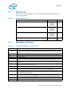
Introduction 1.1 References Material and concepts available in the following documents may be beneficial when reading this document. Table 1-1. Reference Documents Document Location Intel® Xeon® Processor E3-1200 Family Data Sheet Volume One http:// www.intel.com/ Assets/PDF/ datasheet/ 324970.pdf Intel® Xeon® Processor E3-1200 Family Datasheet Volume Two http:// www.intel.com/ Assets/PDF/ datasheet/ 324971.pdf Intel® Xeon® Processor E3-1200 Family Specification Update http:// www.intel.
Introduction Table 1-2. Terms and Descriptions (Sheet 2 of 2) Term Description TCASE_MAX The maximum case temperature as specified in a component specification. TCC Thermal Control Circuit: Thermal monitor uses the TCC to reduce the die temperature by using clock modulation and/or operating frequency and input voltage adjustment when the die temperature is very near its operating limits.
Introduction 12 Thermal/Mechanical Specifications and Design Guidelines
Package Mechanical & Storage Specifications 2 Package Mechanical & Storage Specifications 2.1 Package Mechanical Specifications The processor is packaged in a Flip-Chip Land Grid Array package that interfaces with the motherboard via the LGA1155 socket. The package consists of a processor mounted on a substrate land-carrier. An integrated heat spreader (IHS) is attached to the package substrate and core and serves as the mating surface for processor thermal solutions, such as a heatsink.
Package Mechanical & Storage Specifications 2.1.1 Package Mechanical Drawing Figure 2-2 shows the basic package layout and dimensions. The detailed package mechanical drawings are in Appendix D. The drawings include dimensions necessary to design a thermal solution for the processor. These dimensions include: 1. Package reference with tolerances (total height, length, width, and so on) 2. IHS parallelism and tilt 3. Land dimensions 4. Top-side and back-side component keep-out dimensions 5.
Package Mechanical & Storage Specifications 2.1.3 Package Loading Specifications Table 2-1 provides dynamic and static load specifications for the processor package. These mechanical maximum load limits should not be exceeded during heatsink assembly, shipping conditions, or standard use condition. Also, any mechanical system or component testing should not exceed the maximum limits.
Package Mechanical & Storage Specifications 2.1.7 Processor Materials Table 2-3 lists some of the package components and associated materials. Table 2-3. 2.1.8 Processor Materials Component Material Integrated Heat Spreader (IHS) Nickel Plated Copper Substrate Fiber Reinforced Resin Substrate Lands Gold Plated Copper Processor Markings Figure 2-3 shows the topside markings on the processor. This diagram is to aid in the identification of the processor. Figure 2-3.
Package Mechanical & Storage Specifications 2.1.9 Processor Land Coordinates Figure 2-4 shows the bottom view of the processor package. . Figure 2-4.
Package Mechanical & Storage Specifications 2.2 Processor Storage Specifications Table 2-4 includes a list of the specifications for device storage in terms of maximum and minimum temperatures and relative humidity. These conditions should not be exceeded in storage or transportation. . Table 2-4. Storage Conditions Parameter Description Min Max Notes TABSOLUTE STORAGE The non-operating device storage temperature. Damage (latent or otherwise) may occur when subjected to for any length of time.
LGA1155 Socket 3 LGA1155 Socket This chapter describes a surface mount, LGA (Land Grid Array) socket intended for the processors. The socket provides I/O, power and ground contacts. The socket contains 1155 contacts arrayed about a cavity in the center of the socket with lead-free solder balls for surface mounting on the motherboard. The contacts are arranged in two opposing L-shaped patterns within the grid array.
LGA1155 Socket Figure 3-2. LGA1155 Socket Contact Numbering (Top View of Socket) 39 37 35 40 38 36 34 33 31 32 30 29 30 28 26 24 22 20 18 16 14 12 10 8 6 4 2 27 29 25 27 25 23 23 21 19 21 17 19 17 15 15 13 13 11 28 26 24 22 20 18 16 14 12 11 9 7 5 3 1 A C B 3.
LGA1155 Socket Figure 3-3. LGA1155 Socket Land Pattern (Top View of Board) A C B E D G F J H L K N M R P U T W AA AC AE AG AJ AL AN AR AU AW V Y AB AD AF AH AK AM AP AT AV AY 40 39 38 37 36 35 34 33 32 31 30 36mil (0.9144 mm) 29 28 30 27 29 24 27 23 26 24 26 25 28 25 21 23 22 20 19 22 18 21 17 20 16 19 15 18 17 14 13 16 12 15 11 14 13 122.6 mil (3.
LGA1155 Socket 3.1.1 Suggested Silkscreen Marking for Socket Identification Intel is recommending that customers mark the socket name approximately where shown in Figure 3-4. Figure 3-4. Suggested Board Marking 3.2 Attachment to Motherboard The socket is attached to the motherboard by 1155 solder balls. There are no additional external methods (that is, screw, extra solder, adhesive, and so on) to attach the socket.
LGA1155 Socket 3.3 Socket Components The socket has two main components, the socket body and Pick and Place (PnP) cover, and is delivered as a single integral assembly. Refer to Appendix C for detailed drawings. 3.3.1 Socket Body Housing The housing material is thermoplastic or equivalent with UL 94 V-0 flame rating capable of withstanding 260 °C for 40 seconds which is compatible with typical reflow/rework profiles.
LGA1155 Socket Cover retention must be sufficient to support the socket weight during lifting, translation, and placement (board manufacturing), and during board and system shipping and handling. PnP Cover should only be removed with tools, to prevent the cover from falling into the contacts. The socket vendors have a common interface on the socket body where the PnP cover attaches to the socket body. This should allow the PnP covers to be compatible between socket suppliers.
LGA1155 Socket . Figure 3-7. Package Installation / Removal Features Package Pin 1 Indicator Orientation Notch (2 Places) Alignment Post (2 Places) 3.4.1 Finger/Tool Access (2 Places) Pin 1 Chamfer Socket Standoffs and Package Seating Plane Standoffs on the bottom of the socket base establish the minimum socket height after solder reflow and are specified in Appendix C. Similarly, a seating plane on the topside of the socket establishes the minimum package height. See Section 5.
LGA1155 Socket All markings must withstand 260 °C for 40 seconds (typical reflow/rework profile) without degrading, and must be visible after the socket is mounted on the motherboard. LGA1155 and the manufacturer's insignia are molded or laser marked on the side wall. 3.7 Component Insertion Forces Any actuation must meet or exceed SEMI S8-95 Safety Guidelines for Ergonomics/ Human Factors Engineering of Semiconductor Manufacturing Equipment, example Table R2-7 (Maximum Grip Forces).
Independent Loading Mechanism (ILM) 4 Independent Loading Mechanism (ILM) The ILM has two critical functions: deliver the force to seat the processor onto the socket contacts and distribute the resulting compressive load evenly through the socket solder joints. The mechanical design of the ILM is integral to the overall functionality of the LGA1155 socket. Intel performs detailed studies on integration of processor package, socket and ILM as a system. These studies directly impact the design of the ILM.
Independent Loading Mechanism (ILM) Figure 4-1. ILM Assembly with Installed Processor Hinge / Frame Assy Fasteners Load Lever Load Plate Pin 1 Indicator Shoulder Screw 4.1.2 ILM Back Plate Design Overview The back plate is a flat steel back plate with pierced and extruded features for ILM attach. A clearance hole is located at the center of the plate to allow access to test points and backside capacitors if required. An insulator is pre-applied.
Independent Loading Mechanism (ILM) Figure 4-2. Back Plate Die Cut Insulator Assembly Orientation Feature Pierced & Extruded Thread Features 4.1.3 Shoulder Screw and Fasteners Design Overview The shoulder screw is fabricated from carbonized steel rod. The shoulder height and diameter are integral to the mechanical performance of the ILM. The diameter provides alignment of the load plate. The height of the shoulder ensures the proper loading of the IHS to seat the processor on the socket contacts.
Independent Loading Mechanism (ILM) Figure 4-3. Shoulder Screw Cap 6-32 thread Shoulder 4.2 Assembly of ILM to a Motherboard The ILM design allows a bottoms up assembly of the components to the board. See Figure 4-4 for step by step assembly sequence. 1. Place the back plate in a fixture. The motherboard is aligned with the fixture. 2. Install the shoulder screw in the single hole near Pin 1 of the socket. Torque to a minimum and recommended 8 inch-pounds, but not to exceed 10 inch-pounds. 3.
Independent Loading Mechanism (ILM) . Figure 4-4. ILM Assembly Step 1 Step 3 Note: Step 2 Step 4 Here ILM assembly shown in figure is without ILM cover preinstalled. As indicated in Figure 4-5, the shoulder screw, socket protrusion and ILM key features prevent 180 degree rotation of ILM cover assembly with respect to socket. The result is a specific Pin 1 orientation with respect to ILM lever.
Independent Loading Mechanism (ILM) Figure 4-5. Pin1 and ILM Lever Alignment Features Pin 1 Shoulder Screw Load Lever 4.3 Load plate not shown for clarity ILM Interchangeability ILM assembly and ILM back plate built from the Intel controlled drawings are intended to be interchangeable. Interchangeability is defined as an ILM from Vendor A will demonstrate acceptable manufacturability and reliability with a socket body from Vendor A, B or C.
Independent Loading Mechanism (ILM) 4.5 ILM Cover Intel has developed an ILM Cover that will snap onto the ILM for the LGA115x socket family. The ILM cover is intended to reduce the potential for socket contact damage from operator and customer fingers being close to the socket contacts to remove or install the pick and place cap. The ILM Cover concept is shown in Figure 4-6. The ILM Cover is intended to be used in place of the pick and place cover once the ILM is assembled to the motherboard.
Independent Loading Mechanism (ILM) Figure 4-6. ILM Cover Step 1: PnP Cover installed during ILM assembly Step 2: Remove PnP Cover Step 3: Close ILM As indicated in Figure 4-6, the pick and place cover should remain installed during ILM assembly to the motherboard. After assembly, the pick and place cover is removed, and the ILM mechanism (with the ILM cover installed) closed to protect the contacts.
Independent Loading Mechanism (ILM) Figure 4-7. ILM Cover and PnP Cover Interference As indicated in Figure 4-7, the pick and place cover cannot remain in place and used in conjunction with the ILM Cover. The ILM Cover is designed to interfere and pop off if the pick and place cover is unintentionally left in place. The ILM cover will also interfere and pop off if the ILM is closed with a processor in place in the socket.
Independent Loading Mechanism (ILM) 36 Thermal/Mechanical Specifications and Design Guidelines
LGA1155 Socket and ILM Electrical, Mechanical and Environmental Specifications 5 LGA1155 Socket and ILM Electrical, Mechanical and Environmental Specifications This chapter describes the electrical, mechanical and environmental specifications for the LGA1155 socket and the Independent Loading Mechanism. 5.1 Component Mass Table 5-1. Socket Component Mass Component 5.
LGA1155 Socket and ILM Electrical, Mechanical and Environmental Specifications 5.3 Loading Specifications The socket will be tested against the conditions listed in Chapter 11 with heatsink and the ILM attached, under the loading conditions outlined in this section. Table 5-3 provides load specifications for the LGA1155 socket with the ILM installed. The maximum limits should not be exceeded during heatsink assembly, shipping conditions, or standard use condition.
LGA1155 Socket and ILM Electrical, Mechanical and Environmental Specifications Table 5-4. Electrical Requirements for LGA1155 Socket Parameter Comment <3.6 nH The inductance calculated for two contacts, considering one forward conductor and one return conductor. These values must be satisfied at the worst-case height of the socket.
LGA1155 Socket and ILM Electrical, Mechanical and Environmental Specifications Figure 5-1.
Thermal Specifications 6 Thermal Specifications The processor requires a thermal solution to maintain temperatures within its operating limits. Any attempt to operate the processor outside these operating limits may result in permanent damage to the processor and potentially other components within the system. Maintaining the proper thermal environment is key to reliable, long-term system operation. A complete solution includes both component and system level thermal management features.
Thermal Specifications Section 6.2. To ensure maximum flexibility for future processors, systems should be designed to the Thermal Solution Capability guidelines, even if a processor with lower power dissipation is currently planned. Table 6-1. Processor Thermal Specifications Guidelines8 Max Power Package C1E (W)1,2,6 Max Power Package C3 (W)1,2,6 Max Power Package C6 (W)1,3,6 TTV Thermal Design Power (W)4,5,7 Intel® Xeon® Processor E31280 (95W) 2011D 28 22 5.
Thermal Specifications 6.1.1 Intel® Xeon® Processor E3-1280 (95W)Thermal Profile Figure 6-1. Thermal Test Vehicle Thermal Profile for Intel® Xeon® Processor E3-1280 (95W) Notes: 1. Please refer to Table 6-2 for discrete points that constitute the thermal profile. 2. Refer to Chapter 9 and Chapter 11 for system and environmental implementation details. Table 6-2.
Thermal Specifications Table 6-2. Thermal Test Vehicle Thermal Profile for Intel® Xeon® Processor E3-1280 (95W) (Sheet 2 of 2) Power (W) TCASE_MAX (°C) Power (W) TCASE_MAX (°C) 30 54.1 80 69.1 32 54.7 82 69.7 34 55.3 84 70.3 36 55.9 86 70.9 38 56.5 88 71.5 40 57.1 90 72.1 42 57.7 92 72.7 44 58.3 94 73.3 46 58.9 95 73.6 48 59.5 6.1.2 Intel® Xeon® Processor E3-1200 (80W) Thermal Profile Figure 6-2.
Thermal Specifications Table 6-3. Thermal Test Vehicle Thermal Profile for Intel® Xeon® Processor E3-1200 (80W) Power (W) TCASE_MAX (°C) Power (W) TCASE_MAX (°C) 0 45.1 42 57.7 2 45.7 44 58.3 4 46.3 46 58.9 6 46.9 48 59.5 8 47.5 50 60.1 10 48.1 52 60.7 12 48.7 54 61.3 14 49.3 56 61.9 16 49.9 58 62.5 18 50.5 60 63.1 20 51.1 62 63.7 22 51.7 64 64.3 24 52.3 66 64.9 26 52.9 68 65.5 28 53.5 70 66.1 30 54.1 72 66.7 32 54.7 74 67.3 34 55.
Thermal Specifications 6.1.3 Intel® Xeon® Processor E3-1260L (45W) Thermal Profile Figure 6-3. Thermal Test Vehicle Thermal Profile for Intel® Xeon® Processor E3-1260L (45W) Notes: 1. Please refer to Table 6-4 for discrete points that constitute the thermal profile. 2. Refer to Chapter 9 and Chapter 11 for system and environmental implementation details. Table 6-4.
Thermal Specifications 6.1.4 Intel® Xeon® Processor E3-1220L (20W) Thermal Profile Figure 6-4. Thermal Test Vehicle Thermal Profile for Intel® Xeon® Processor E3-1220L (20W) Notes: 1. Please refer to Table 6-5 for discrete points that constitute the thermal profile. 2. Refer to Chapter 9 and Chapter 11 for system and environmental implementation details. Table 6-5.
Thermal Specifications 6.1.5 Intel® Xeon® Processor E3-1200 (95W) with Integrated Graphics Thermal Profile Figure 6-5. Thermal Test Vehicle Thermal Profile for Intel® Xeon® Processor E3-1200 (95W) with Integrated Graphics Notes: 1. Please refer to Table 6-6 for discrete points that constitute the thermal profile. 2. Refer to Chapter 11 for system and environmental implementation details. Table 6-6.
Thermal Specifications Table 6-6. Thermal Test Vehicle Thermal Profile for Intel® Xeon® Processor E3-1200 (95W) with Integrated Graphics (Sheet 2 of 2) Power (W) 6.1.6 TCASE_MAX (°C) Power (W) TCASE_MAX (°C) 24 52.1 74 66.6 26 52.6 76 67.1 28 53.2 78 67.7 30 53.8 80 68.3 32 54.4 82 68.9 34 55.0 84 69.5 36 55.5 86 70.0 38 56.1 88 70.6 40 56.7 90 71.2 42 57.3 92 71.8 44 57.9 94 72.4 46 58.4 95 72.6 48 59.
Thermal Specifications Table 6-7. Thermal Solution Performance above TCONTROL for the Intel® Xeon® Processor E3-1280 (95W) (Sheet 2 of 2) TAMBIENT1 ΨCA at DTS = TCONTROL2 ΨCA at DTS = -13 37.0 0.445 0.385 36.0 0.462 0.396 35.0 0.480 0.406 34.0 0.498 0.417 33.0 0.516 0.427 32.0 0.534 0.438 31.0 0.552 0.448 30.0 0.569 0.459 29.0 0.587 0.469 28.0 0.605 0.480 27.0 0.623 0.491 26.0 0.641 0.501 25.0 0.659 0.512 24.0 0.676 0.522 23.0 0.694 0.533 22.0 0.712 0.
Thermal Specifications Table 6-8. Thermal Solution Performance above TCONTROL for the Intel® Xeon® Processor E3-1200 (80W) (Sheet 2 of 2) TAMBIENT1 ΨCA at DTS = TCONTROL2 ΨCA at DTS = -13 32.0 0.578 0.464 31.0 0.599 0.476 30.0 0.620 0.489 29.0 0.641 0.501 28.0 0.662 0.514 27.0 0.683 0.526 26.0 0.705 0.539 25.0 0.726 0.551 24.0 0.747 0.564 23.0 0.768 0.576 22.0 0.789 0.589 21.0 0.811 0.601 20.0 0.832 0.614 Notes: 1.
Thermal Specifications Table 6-9. Thermal Solution Performance above TCONTROL for the Intel® Xeon® Processor E3-1260L (45W) (Sheet 2 of 2) TAMBIENT1 ΨCA at DTS = TCONTROL2 ΨCA at DTS = -13 27.0 0.982 0.702 26.0 1.019 0.724 25.0 1.057 0.747 24.0 1.095 0.769 23.0 1.132 0.791 22.0 1.170 0.813 21.0 1.208 0.836 20.0 1.245 0.858 Notes: 1. The ambient temperature is measured at the inlet to the processor thermal solution. 2.
Thermal Specifications Table 6-10. Thermal Solution Performance above TCONTROL for the Intel® Xeon® Processor E3-1220L (20W) (Sheet 2 of 2) TAMBIENT1 ΨCA at DTS = TCONTROL2 ΨCA at DTS = -13 28.0 3.882 2.475 27.0 3.967 2.525 26.0 4.052 2.575 25.0 4.136 2.625 Notes: 1. The ambient temperature is measured at the inlet to the processor thermal solution. 2. This column can be expressed as a function of TAMBIENT by the following equation: YCA = 0.45+ (68.5 - TAMBIENT) x 0.0847 3.
Thermal Specifications 6.1.7 Thermal Metrology The maximum TTV case temperatures (TCASE-MAX) can be derived from the data in the appropriate TTV thermal profile earlier in this chapter. The TTV TCASE is measured at the geometric top center of the TTV integrated heat spreader (IHS). Figure 6-6 illustrates the location where TCASE temperature measurements should be made. See Figure B-17 for drawing showing the thermocouple attach to the TTV package. Figure 6-6.
Thermal Specifications control, similar to Thermal Monitor 2 (TM2) in previous generation processors) involves the processor reducing its operating frequency (via the core ratio multiplier) and input voltage (via the VID signals). This combination of lower frequency and VID results in a reduction of the processor power consumption.
Thermal Specifications take place. This sequence of temperature checking and Frequency/VID reduction will continue until either the minimum frequency has been reached or the processor temperature has dropped below the TCC activation point. If the processor temperature remains above the TCC activation point even after the minimum frequency has been reached, then clock modulation (described below) at that minimum frequency will be initiated.
Thermal Specifications A small amount of hysteresis has been included to prevent rapid active/inactive transitions of the TCC when the processor temperature is near its maximum operating temperature. Once the temperature has dropped below the maximum operating temperature, and the hysteresis timer has expired, the TCC goes inactive and clock modulation ceases. 6.2.2.
Thermal Specifications transitioning to the minimum frequency and corresponding voltage (using Freq/VID control). Clock modulation is not activated in this case. The TCC will remain active until the system de-asserts PROCHOT#. Use of PROCHOT# in bi-directional mode can allow VR thermal designs to target maximum sustained current instead of maximum current. Systems should still provide proper cooling for the VR, and rely on PROCHOT# only as a backup in case of system cooling failure.
Thermal Specifications • The number of cores operating in the C0 state. • The estimated current consumption. • The estimated power consumption. • The temperature. Any of these factors can affect the maximum frequency for a given workload. If the power, current, or thermal limit is reached, the processor will automatically reduce the frequency to stay with its TDP limit. Note: Intel Turbo Boost Technology processor frequencies are only active if the operating system is requesting the P0 state. 6.3.
Thermal Specifications 6.4.1 Intel® Turbo Boost Technology Power Control and Reporting When operating in the turbo mode, the processor will monitor its own power and adjust the turbo frequency to maintain the average power within limits over a thermally significant time period. The package, processor core, and graphic core powers are estimated using architectural counters and do not rely on any input from the platform.
Thermal Specifications 6.4.2 Package Power Control The package power control allows for customization to implement optimal turbo within platform power delivery and package thermal solution limitations. Figure 6-8. Package Power Control Turbo Algorithm Response Time Time System Thermal Response 6.4.3 Power Plane Control The processor core and graphics core power plane controls allow for customization to implement optimal turbo within voltage regulator thermal limitations.
Thermal Specifications 62 Thermal/Mechanical Specifications and Design Guidelines
PECI Interface 7 PECI Interface 7.1 Platform Environment Control Interface (PECI) 7.1.1 Introduction PECI uses a single wire for self-clocking and data transfer. The bus requires no additional control lines. The physical layer is a self-clocked one-wire bus that begins each bit with a driven, rising edge from an idle level near zero volts. The duration of the signal driven high depends on whether the bit value is a logic ‘0’ or logic ‘1’.
PECI Interface 64 Thermal/Mechanical Specifications and Design Guidelines
Sensor Based Thermal Specification Design Guidance 8 Sensor Based Thermal Specification Design Guidance The sensor based thermal specification presents opportunities for the system designer to optimize the acoustics and simplify thermal validation. The sensor based specification utilizes the Digital Thermal Sensor information accessed via the PECI interface.
Sensor Based Thermal Specification Design Guidance Figure 8-1. Comparison of Case Temperature vs. Sensor Based Specification Ta = 45.1 °C Tcontrol Ta = 30 °C Ψ-ca = 0.292 Power TDP Current Specification (Case Temp) Ψ-ca = 0.448 Ψ-ca = 0.
Sensor Based Thermal Specification Design Guidance 8.2 Sensor Based Thermal Specification The sensor based thermal specification consists of two parts. The first is a thermal profile that defines the maximum TTV TCASE as a function of TTV power dissipation. The thermal profile defines the boundary conditions for validation of the thermal solution. The second part is a defined thermal solution performance (ΨCA) as a function of the DTS value as reported over the PECI bus when DTS is greater than TCONTROL.
Sensor Based Thermal Specification Design Guidance Note: This graph is provided as a reference, the complete thermal specification is in Chapter 6. 8.2.2 Specification When DTS value is Greater than TCONTROL The product specification provides a table of ΨCA values at DTS = TCONTROL and DTS = -1 as a function of TAMBIENT (inlet to heatsink). Between these two defined points, a linear interpolation can be done for any DTS value reported by the processor.
Sensor Based Thermal Specification Design Guidance 8.3.2 Thermal Design and Modelling Based on the boundary conditions, the designer can now make the design selection of the thermal solution components. The major components that can be mixed are the fan, fin geometry, heat pipe or air duct design. There are cost and acoustic trade-offs the customer can make. To aide in the design process Intel provides TTV thermal models. Please consult your Intel Field Sales Engineer for these tools. 8.3.
Sensor Based Thermal Specification Design Guidance • When the DTS value is at or below TCONTROL, the fans can be slowed down - just as with prior processors. • When DTS is above TCONTROL, FSC algorithms will use knowledge of TAMBIENT and ΨCA vs. RPM to achieve the necessary level of cooling. DTS 1.1 provides another option to do fan speed control without the Tambient data. Please refer to Section 8.4.1 for more details.This chapter will discuss two implementations.
Sensor Based Thermal Specification Design Guidance 8.4.1 DTS 1.1 A New Fan Speed Control Algorithm without TAMBIENT Data In most system designs incorporating processor ambient inlet data in fan speed control adds design and validation complexity with a possible BOM cost impact to the system. A new fan speed control methodology is introduced to improve system acoustics without needing the processor inlet ambient information. The DTS 1.
Sensor Based Thermal Specification Design Guidance Figure 8-3. DTS 1.1 Definition Points Table 8-1. DTS 1.1 Thermal Solution Performance above TCONTROL Processor TDP ψCA at DTS = TCONTROL1,2 ψCA at DTS = -1 At System ambient_max= 40C ψCA at DTS = -1 At System ambient_max= 45C ψCA at DTS = -1 At System ambient_max= 50C 95W(no graphic) 0.569 0.354 0.300 0.248 95W(with graphic) 0.564 0.343 0.291 0.238 80W (no graphic) 0.620 0.364 0.300 0.238 45W(with graphic) 0.869 0.413 0.301 0.
Sensor Based Thermal Specification Design Guidance 8.5 System Validation System validation should focus on ensuring the fan speed control algorithm is responding appropriately to the DTS values and TAMBIENT data in the case of DTS 1.0 as well as any other device being monitored for thermal compliance. Since the processor thermal solution has already been validated using the TTV to the thermal specifications at the predicted TAMBIENT, additional TTV based testing in the chassis is not necessary.
Sensor Based Thermal Specification Design Guidance 74 Thermal/Mechanical Specifications and Design Guidelines
1U Thermal Solution 9 1U Thermal Solution Note: The thermal mechanical solution information shown in this document represents the current state of the data and may be subject to modification.The information represents design targets, not commitments by Intel.
1U Thermal Solution Figure 9-1. 1U Collaboration Heatsink Performance Curves Collaboration thermal solution Ψca (mean+3sigma) is computed to 0.319°C/W at the airflow of 15 CFM. As the Table 9-1 shown when TLA is 40 °C, equation representing thermal solution of this heatsink is calculated as: Y=0.319*X+40 where, Y = Processor TCASE Value (°C) X = Processor Power Value (W) Table 9-2 shows thermal solution performance is compliant with Intel® Xeon® processor E3-1280 (95W) TTV thermal profile specification.
1U Thermal Solution Figure 9-2. 1U Collaboration Heatsink Performance Curves Table 9-2. Comparison between TTV Thermal Profile and Thermal Solution Performance for Intel® Xeon® Processor E3-1280 (95W) (Sheet 1 of 2) Power (W) TTV TCASE_MAX (°C) Thermal Solution TCASE_MAX (°C) Power (W) TTV TCASE_MAX (°C) Thermal Solution TCASE_MAX (°C) 0 45.1 40.0 50 60.1 56.0 2 45.7 40.6 52 60.7 56.6 4 46.3 41.3 54 61.3 57.2 6 46.9 41.9 56 61.9 57.9 8 47.5 42.6 58 62.5 58.5 10 48.
1U Thermal Solution Table 9-2. 9.2.2 Comparison between TTV Thermal Profile and Thermal Solution Performance for Intel® Xeon® Processor E3-1280 (95W) (Sheet 2 of 2) Power (W) TTV TCASE_MAX (°C) Thermal Solution TCASE_MAX (°C) Power (W) TTV TCASE_MAX (°C) Thermal Solution TCASE_MAX (°C) 36 55.9 51.5 86 70.9 67.4 38 56.5 52.1 88 71.5 68.1 40 57.1 52.8 90 72.1 68.7 42 57.7 53.4 92 72.7 69.3 44 58.3 54.0 94 73.3 70.0 46 58.9 54.7 95 73.6 70.3 48 59.5 55.
1U Thermal Solution 9.2.3 Assembly Figure 9-3. 1U Collaboration Heatsink Assembly The assembly process for the 1U collaboration heatsink with application of thermal interface material begins with placing back plate in a fixture. The motherboard is aligned with fixture. Next is to place the heatsink such that the heatsink fins are parallel to system airflow. While lowering the heatsink onto the IHS, align the four captive screws of the heatsink to the four holes of motherboard.
1U Thermal Solution 9.3 1U Reference Heatsink 9.3.1 Heatsink Performance For 1U reference heatsink, see Appendix B for detailed drawings. Figure 9-4 shows ΨCAand pressure drop for the 1U reference heatsink versus the airflow provided. Bestfit equations are provided to prevent errors associated with reading the graph. Figure 9-4. 1U Reference Heatsink Performance Curves This 1U Reference thermal solution Ψca(mean+3sigma) is computed to 0.353°C/W at the airflow of 15.
1U Thermal Solution 9.3.3 Assembly The assembly process is same as the way described in Section 9.2.3, please refer to it for more details. 9.4 Geometric Envelope for 1U Thermal Mechanical Design Figure 9-5. KOZ 3-D Model (Top) in 1U Server 9.5mm Maximum Component Height (5 places) 1.6mm Maximum Component Height (2 places) 2.5mm Maximum Component Height (6 places) 9.5 2.07mm Maximum Component Height (1 place) 1.
1U Thermal Solution Figure 9-6. TTV Die Size and Orientation 37.5 Package Centerline 10.94 Drawing Not to Scale All Dimensions in mm § 82 37.5 10.
Active Tower Thermal Solution 10 Active Tower Thermal Solution 10.1 Introduction This active tower thermal solution is intended for system integrators who build systems from baseboards and standard components. This chapter documents baseboard and system requirements for the cooling solution. It is particularly important for OEMs that manufacture baseboards for system integrators. Note: Unless otherwise noted, all figures in this chapter are dimensioned in millimeters and inches [in brackets].
Active Tower Thermal Solution 10.2 Mechanical Specifications 10.2.1 Cooling Solution Dimensions This section documents the mechanical specifications. Figure 10-1 shows a mechanical representation of the solution. Clearance is required around the fan heatsink to ensure unimpeded airflow for proper cooling. The physical space requirements and dimensions for the processor with assembled thermal solution are shown in Figure 10-2 (Side View), and Figure 10-3 (Top View).
Active Tower Thermal Solution Figure 10-3. Physical Space Requirements for the Solution (top view) Note: 10.2.2 Diagram does not show the attached hardware for the clip design and is provided only as a mechanical representation. Retention Mechanism and Heatsink Attach Clip Assembly The thermal solution requires a heatsink attach clip assembly, to secure the processor and fan heatsink in the baseboard socket. 10.3 Electrical Requirements 10.3.
Active Tower Thermal Solution The power header on the baseboard must be positioned to allow the fan power cable to reach it. The power header identification and location should be documented in the platform documentation, or on the system board itself. Figure 10-5 shows the location of the fan power connector relative to the processor socket. The baseboard power header should be positioned within 110 mm [4.33 inches] from the center of the processor socket. Figure 10-4.
Active Tower Thermal Solution 10.4 Cooling Requirements The processor may be directly cooled with a fan heatsink. However, meeting the processor's temperature specification is also a function of the thermal design of the entire system, and ultimately the responsibility of the system integrator. The processor temperature specification is found in Chapter 6 of this document.
Active Tower Thermal Solution 88 Thermal/Mechanical Specifications and Design Guidelines
Thermal Solution Quality and Reliability Requirements 11 Thermal Solution Quality and Reliability Requirements 11.1 Reference Heatsink Thermal Verification Each motherboard, heatsink and attach combination may vary the mechanical loading of the component. Based on the end user environment, the user should define the appropriate reliability test criteria and carefully evaluate the completed assembly prior to use in high volume.
Thermal Solution Quality and Reliability Requirements 11.2.1 Recommended Test Sequence Each test sequence should start with components (that is, baseboard, heatsink assembly, and so on) that have not been previously submitted to any reliability testing. Prior to the mechanical shock & vibration test, the units under test should be preconditioned for 72 hours at 45 ºC. The purpose is to account for load relaxation during burn-in stage.
Thermal Solution Quality and Reliability Requirements 11.3 Material and Recycling Requirements Material shall be resistant to fungal growth. Examples of non-resistant materials include cellulose materials, animal and vegetable based adhesives, grease, oils, and many hydrocarbons.
Thermal Solution Quality and Reliability Requirements 92 Thermal/Mechanical Specifications and Design Guidelines
Component Suppliers A Component Suppliers Note: The part numbers listed below identifies the reference components. End-users are responsible for the verification of the Intel enabled component offerings with the supplier. These vendors and devices are listed by Intel as a convenience to Intel's general customer base, but Intel does not make any representations or warranties whatsoever regarding quality, reliability, functionality, or compatibility of these devices.
Component Suppliers Table A-4. LGA1155 Socket and ILM Components (Sheet 2 of 2) Item Table A-5. Intel PN Foxconn Molex Tyco Lotes LGA115x ILM cover only G12451-001 012-1000-5377 475973003 1-2134503-1 ACA-ZIF-127P01 LGA115x ILM Back Plate (with screws) E36143-002 PT44P19-6401 475969930 2069838-2 DCA-HSK-144Y09 1U ILM Back Plate (with Screws) E66807-001 PT44P18-6401 N/A N/A DCA-HSK-157Y03 Supplier Contact Information Supplier Contact Phone Email AVC (Asia Vital Components Co.
Mechanical Drawings B Mechanical Drawings Table B-1 lists the mechanical drawings included in this appendix. Table B-1.
Mechanical Drawings Figure B-1.
Mechanical Drawings Figure B-2.
3.18 3.18 19.50 C C 15.92 8.97 9.26 51.00 B A SEE DETAIL 2.50 8.12 2 17.00 5 8.97 B 9.26 A 8 MINIMUM OPEN ANGLE TO CLEAR LOAD PLATE 7 MAXIMUM OPEN ANGLE TO OPEN LOAD PLATE 6 MOTHERBOARD BACKSIDE COMPONENT KEEP-IN (R 65.21 ) 130.0 8 (R 46.51 ) 5.00 SECTION B-B ( 49.50 ) 3X 21.25 42.50 C LOAD PLATE OPENING MOTION SPACE 70.37 3.75 CLEARANCE NEEDED FOR WIRE TRAVEL SECTION A-A 3X 2.
0.00 PIN 1 35.21 40.71 25.81 25.50 C 0.00 18.00 R3.50 TOP SIDE PCB ILM MOUNTING HOLES 18.00 Thermal/Mechanical Specifications and Design Guidelines ( 47.50 ) 3X 5 FINGER ACCESS COMPONENT KEEPOUT AREA B +0.05 NPTH -0.03 B C ( 10.50 ) 3.80 0.1 6.00 +0.05 -0.03 NO ROUTE ON PRIMARY & SECONDARY SIDES 3X 4.70 NO ROUTE ON ALL OTHER LAYERS COPPER PAD ON PRIMARY SIDE, NON-GROUNDED. COPPER PAD CAN INSET MAXIMUM OF .127MM FROM THE NO ROUTE EDGE 3X B 25.
3 A 5 4 1 SECTION A-A 5 3 2 6 4 3 A 4 3 2 1 1 4 4 4 PART NUMBER DATE FINISH APPROVED BY MATERIAL 2 DATE CHECKED BY - DESCRIPTION R 2200 MISSION COLLEGE BLVD. P.O.
Thermal/Mechanical Specifications and Design Guidelines 3 24.85 4 4X 2.5 8 0.076 5.5 3 FLATNESS ZONE 6 55.7 0 75 0 -0.4 3 11/01/08 THIRD ANGLE PROJECTION DATE FINISH APPROVED BY MATERIAL 2 DATE CHECKED BY - SEE NOTES 07/15/08 SEE NOTES DATE 07/15/08 DRAWN BY JUN LU DESCRIPTION R 2200 MISSION COLLEGE BLVD. P.O.
Mechanical Drawings Figure B-7.
Mechanical Drawings Figure B-8.
3 0.35 +0.05 0 5 SEE DETAIL A C 6 3 2X 5 2 5 7 0.32 6 ( 5.6 ) 0 -0.1 5 7 DATE DATE FINISH CHECKED BY APPROVED BY MATERIAL DESCRIPTION SCALE: 1:1 2200 MISSION COLLEGE BLVD. P.O. BOX 58119 SANTA CLARA, CA 95052-8119 E50686 1 DO NOT SCALE DRAWINGSHEET 1 OF 1 SIZE DRAWING NUMBER C R SCALE 5:1 B REV SCREW,SHOULDER, M3 X 0.5, FOXHOLLOW TITLE EASD-SH DEPARTMENT PARTS LIST SEE NOTES 07/20/08 SEE NOTES DATE 07/20/08 DRAWN BY JUN LU JUN LU DATE DESIGNED BY 2 3.
Mechanical Drawings Figure B-10.
Mechanical Drawings Figure B-11.
Mechanical Drawings Figure B-12.
3 75 C 4 ( 89.25 ) 6 A 5 A 4 75 SECTION A-A ( 74.05 ) 6 ( 68.55 ) 6 ( 89.25 ) 6 ( 92.25 ) 6 3 A 2 1 1 DATE FINISH APPROVED BY MATERIAL 2 DATE CHECKED BY - DESCRIPTION R 2200 MISSION COLLEGE BLVD. P.O.
Mechanical Drawings Figure B-14.
Mechanical Drawings Figure B-15.
Thermal/Mechanical Specifications and Design Guidelines 3 6 4 6 A 0.05 7 SECTION A-A 3.8 6 5.55 0.13 7 B C 2 3 ADDED PLATING CORROSION REQUIREMENT REDEFINE THE HEIGHT OF STUD INITIAL RELEASE TOP THIRD ANGLE PROJECTION DATE FINISH APPROVED BY MATERIAL 2 DATE CHECKED BY - SEE NOTES 04/10/08 SEE NOTES DATE 04/10/08 DRAWN BY JUN LU DESCRIPTION SCALE: 1:1 2200 MISSION COLLEGE BLVD. P.O.
A B 3 A C 4 B PACKAGE CENTER SECTION A-A 7. 0.381 ±0.038 0.0150 ±0.0015 0.51 ±0.08 0.020 ±0.003 3 FINISH: UNLESS OTHERWISE SPECIFIED: DIMENSIONS ARE IN INCHES. TOLERANCES: TOL: .X 0.2 ANGLES: 0.5 .XX 0.05 0.001 .XXX INTERPRET DIM AND TOL PER ASME Y14.5M-1994. MATERIAL: PACKAGE CENTER REFERENCED FROM PACKAGE EDGES PACKAGE EDGES NOTES: UNLESS OTHERWISE SPECIFIED 1. NORMAL AND LATERAL LOADS ON THE IHS MUST BE MINIMIZED DURING MACHINING. 2.
Thermal/Mechanical Specifications and Design Guidelines A B C D E F G H 8 7 6 5 4 3 2 8 7 6 5 1. THIS DRAWING TO BE USED IN CONJUNCTION WITH THE SUPPLIED 3D DATABASE FILE. ALL DIMENSIONS AND TOLERANCES ON THIS DRAWING TAKE PRECEDENCE OVER SUPPLIED FILE. 2. UNLESS OTHERWISE NOTED, TOLERANCES ON DIMENSIONED FEATURES ARE AS IN TOLERANCE BLOCK. 3 CRITICAL TO FUNCTION (CTF). 4. MATERIAL: LOW CARBON STEEL, MIN HARDNESS - ROCKEWELL HARDNESS B70. 5. PLATING: 2 MICRON MIN.
A B C D E F G H 8 7 6 5 4 3 2 UNLESS OTHERWISE NOTED, TOLERANCES ON DIMENSIONS AND UNDIMENSIONED FEATURES ARE AS IN TABLE. CRITICAL TO FUNCTION (CTF) 2. 3 4. 8 +/- 0.25 mm 6 +/- 0.15 mm 1 - 10 mm 7 TOLERANCE 0 - 1 mm 5 4 MAX 2.41 PHYSICAL PAN HEAD HEIGHT DELETED 8. FEATURE SIZE REFERENCE AND UNDIMENSIONED FEATURES MAY BE MODIFIED PER INTEL APPROVAL. 7. 6.
Socket Mechanical Drawings C Socket Mechanical Drawings Table C-1 lists the mechanical drawings included in this appendix. Table C-1.
Socket Mechanical Drawings Figure C-1. Socket Mechanical Drawing (Sheet 1 of 4) 116 GuidelinesDocument Number: 448776 Rev. 2.
Socket Mechanical Drawings Figure C-2.
Socket Mechanical Drawings ( Figure C-3. Socket Mechanical Drawing (Sheet 3 of 4) 118 GuidelinesDocument Number: 448776 Rev. 2.
Socket Mechanical Drawings Figure C-4.
Socket Mechanical Drawings 120 GuidelinesDocument Number: 448776 Rev. 2.
Package Mechanical Drawings D Package Mechanical Drawings Table D-1 lists the mechanical drawings included in this appendix. Table D-1.
Package Mechanical Drawings Figure D-1.
Package Mechanical Drawings Figure D-2. Processor Package Drawing (Sheet 2of 2) .
Package Mechanical Drawings 124 Thermal/Mechanical Specifications and Design Guidelines