J2 650 Integrated Touchscreen Computer System Manual August 2008
Contents Overview ............................................................................................................................ 5 Specification....................................................................................................................... 7 Unique Features ................................................................................................................ 9 Intel’s Desktop Processor Socket LGA 775 ............................................................
Removing the Back Cover ............................................................................................ 28 Changing the System Board.......................................................................................... 29 Adding Memory ............................................................................................................ 31 Changing the Processor................................................................................................. 31 Accessing the CF Card...
Applications .................................................................................................................. 58 RAID ................................................................................................................................ 59 RAID Overview ............................................................................................................ 59 AHCI .................................................................................................................
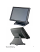
Overview The 650 from J2 is the most high performance integrated Point of Sale computer available to date. This amazingly versatile unit can be configured as either a low power fan less thin client terminal; as a midrange thick client terminal; or even as a Dual Core high speed server with RAID. Product versatility and reliability are the key strengths of this 650 system.
50 System Manual (Draft) Version 0.
Specification Main board Intel Desktop Processors LGA775, 1066 MHz FSB, 65W TDP max CPU Support System Memory Intel 1.
Power Power Adapter 19VDC, 135W, 100-240 VAC,50~60Hz, 2.2A Optional Peripheral MSR 3 Track ( on PS2 port, wedge type ) iButton Dallas Key iButton ( on PS2 port, wedge type ) 2-in-1 MSR MSR 3 track (PS2) / Finger Print (USB) Second Display optional 8.4”, 10.4” or 12.
Unique Features The 650 truly has some unique features not hitherto seen on an integrated touch screen computer before. These features allow for a great deal of versatility in how the 650 can be configured and used. A quick list of unique features is as follows: Intel’s Desktop Processor Socket LGA 775 By using the new generation of Intel’s green processors and chipsets, a very wide range of processors can be used in the 650 system. From a Celeron single core processor running fan less at 1 GHz to a 2.
Automatic LCD Brightness Control Another innovative feature of the 650 is its use of a light sensor to control the LCD brightness. A light sensor is built into the unit and can detect when a room is darkened. It will automatically dim the LCD so that it is not too bright. This patent pending feature is also unique to J2. UPS Not your ordinary UPS, the J2 650 UPS is a DC, not an AC UPS. The UPS fits conveniently into the base of the unit.
System Configurations The 650 can be ordered or upgraded to many possible configurations. Selecting the right combination of memory, processor, hard drive(s) and software drivers can dramatically change the performance of the 650 system. For a lot of users the standard 650 1.6GHz processor and 512MB of memory is fine, but some applications require a lot more horse power. J2 will be happy to help you determine what you may require from the 650 in the most cost effective way.
Processors currently supported on the 650 CPU # Description (all are desktop processors) Cores 420 Celeron 440 Family 1 1.
I/O Ports The 650 is an integrated design with all the electronics in the head. Most I/O ports are accessible in the cable well at the bottom of the unit. A cover plate is provided to cover the cables. I/O Panel Off / On Button The Off /On button is located in the cable well, as shown. This button is located near the side to prevent accidental powering down by the user. The function of the button can be controlled by the OS.
Hard Disks Two 2.5 inch SATA hard drives (HDD) are supported. These drives can be configured as standard hard drives or as a RAID array. The SATA interface can support data transfer rates up to 3.0 Gb/s and supports AHCI and Hot Swapping of hard drives. The HDDs can easily be accessed by removing a panel on the left side of the unit. HDDs can be installed or removed in seconds by removing one screw. A carrying tray (two of which are supplied with the 650) clips onto a new drive without tools.
Compact Flash The 650 has one Type I/II Compact Flash (CF) memory slot. This slot is only for IDE mode CF devices and is easily accessed on the left side of the unit. The CF card is mapped to a SATA port and supports PIO Mode 0-4. The CF card is normally used for thin client configurations using XPe, CE, WEPOS, or Linux operating systems. Compact Flash access panel Touch Screen The 650RT uses a five-wire touch screen rated at 35 million touches per point.
System Board POS computers typically have a desired lifespan of 10 years or longer, therefore product quality is of the utmost importance. The 650 electronics are built with high-end components to ensure reliability and long lasting product performance. The system board is designed for quick replacement and only has one connection, an edge pin connector, to which all motherboard connections are made. System board LCD Display The LCD display for the 650 is a 1024 x 768 resolution display with 16.
Secondary Display Port A secondary video display is supported on the 650 and can be set as the primary or secondary display. Secondary video displays can be configured as a Twin, Intel Dual Display Clone, or Extended Desktop. Most all monitor resolutions from 640 x 480 to 2560 x 2048 are supported via the Secondary Display Port. The secondary display can also be rotated 90, 180 or 270 degrees. A number of additional features are supported depending on the capabilities of the monitor.
Serial ports The 650 has three external RS232 serial ports, two of which can be powered COM2 and COM3. The serial ports are standard PC RS232 ports with a DB9 male connector. The serial ports, in a normal configuration, are mapped to COM 1-3. COM ports 2 and 3 can supply power to an external device when required, like the optional J2 Customer Display. Voltage, +12, is supplied on pin 9 (RI) of the DB9 connector. The maximum current is 500ma and is over-current protected.
Parallel Port The 650 has one Parallel Printer Port located in the connector well (shown below) which supports SPP, ECP and EPP printer modes. The mode can be changed in the BIOS setup. Parallel Port USB ports The 650 has five external and three internal USB 2.0 ports. Of the five external ports (see below) four ports are located in the cable well and one is located on the left side of the unit for easy access.
Ethernet Connection The 650 uses the Realtek 8111C Gigabit Ethernet controller. The Ethernet connector is located in the cable well, as shown below. The Ethernet controller supports Wake on LAN, the BIOS supports a PXE boot ROM as well. There are two LEDs on the LAN connector: the Green LED lights up when the LINK signal is present and the Amber LED lights comes on when there is LAN activity. Kensington Security Slot There are two Kensington Security Slots (lock slots) on the 650. (Please see below).
Audio The 650 uses the VIA1708B HD audio controller. There is one internal speaker. Both a microphone jack and a headset jack are located on the left side of the 650, as seen below, which allows for the connection of a microphone and headset or audio out to other devices. Audio Jack Location Printer Power Port The Printer Power Port allows an industry standard POS printer to be powered from the 650 and eliminates the need for a separate external power supply for the printer.
Cash Drawer Ports The 650 is equipped standard with two Cash Drawer ports. These ports are located in the cable well and use the industry standard RJ-11 connector and pin out (illustrated below). Cash Drawer Ports Cash Drawer Pin Assignment 6 1 Pin 1 2 3 4 5 6 Signal GND SOLENOID STATUS 24V NC GND The application may address the Cash Drawer port in a number of ways. They are: 1) Using the J2 supplied OPOS drivers for Vista, XP, WEPOS and XP Embedded. 2) Using the J2 supplied Virtual COM port for CE.
bits of COM5, and the drawer open/close status will be reflected on the CTS and RI bits, either bit may be used. This virtual COM port driver is designed to work the same as most serial cash drawers so that drivers for a serial cash drawer should work if mapped to the correct COM port, normally COM5 in the 650 system. The cash drawer can directly be accessed through two I/O ports, 280 hex and 281 hex. Port 280 hex is an output only port and fires the cash drawer when toggled.
Service Removing the Head from the Base A countertop base is supplied standard with the unit. The base is easily attached to the unit by sliding the unit onto the base’s mounting slots. One screw point is used to secure the base to the unit and is accessed from the bottom of the 650. To remove the base from the unit, first remove the Base Locking Screw at the bottom of the base as shown in the picture. Base Locking Screw To remove the base, pull it towards the bottom of the unit as shown in the picture.
Removing the Power Supply The power supply is normally located in the counter top base. When using a wall mount bracket or the J2 UPS, the power supply would be external from the unit. To remove the power supply from the base, one screw needs to be removed. With the screw removed the power supply and mounting bracket can be removed by sliding the bracket, then tilting the power supply and bracket up. Screw location 650 System Manual (Draft) Version 0.
Wall Mounting Bracket A wall mount/VESA adapter bracket is supplied standard with the 650 unit. This bracket allows the unit to be mounted to a wall or other surface. The wall mounting bracket is a one piece bracket with four mounting holes (plus VESA mounting holes: see next section). This mounting bracket would first be attached to the mounting surface, and then the unit would be slid on to the mounting bracket hooks.
VESA Mounting The 650 unit also supports the industry standard 75mm VESA mounting. J2 offers a Pole Mount option that uses the VESA standard. There are also a number of third party vendors that make many different types of 75mm VESA mounts, allowing for a myriad of mounting options. The VESA mounting pattern is supported via the wall mounting plate which has the 75mm mounting pattern as shown below. Four 4mm x 8mm screws are used (supplied) to secure the bracket to the VESA mounting bracket.
Removing the Back Cover The following steps show how to disassemble the 650 for servicing: On a clean, protected surface, place the unit screen-side down. Remove the two cover screws as shown. Carefully lift the back cover as shown. Remove two screws as shown Carefully tilt up the back cover Note: The 650 was designed so that the internals of the unit could be accessed without having to remove the mounting base or the mounting bracket of the unit. 650 System Manual (Draft) Version 0.
Changing the System Board *Special Note: An anti-static workplace with proper grounding is required when changing the System Board. First remove the back cover. There are 5 screws that hold the system board in place that will need to be removed; the middle screw is the captive type and only needs to be loosened. The CF card guide also needs to be removed. (see photo below) Screw location System Board 650 System Manual (Draft) Version 0.
After the screws are removed the system board can be unplugged from its connector. While using the I/O bracket to pull on, slide the board out towards the bottom of the unit as shown. When reinstalling the system board make sure the locking tabs on the bottom of the board lock into their mating slots. 650 System Manual (Draft) Version 0.
Adding Memory Note: An anti static workplace with proper grounding is required when adding memory. Remove the back cover. You can now access the two memory sockets; the order in which the memory is populated does not matter. Memory sockets Changing the Processor To change the processor, first start by working in an anti-static workplace with proper grounding. Remove the back cover by removing the two screws; now remove the black plastic fan duct (as shown below).
Accessing the CF Card Remove screw as shown Lift cover out of the way Insert the Compact Flash card ensuring the card slides in on the guides When inserting the card do not force it. Replace cover when installed. 650 System Manual (Draft) Version 0.
Accessing the Hard Drives Remove cover screw as shown Remove cover Remove or insert drive as needed The HDD may be hot swapped when in a RAID 1 configuration. In non RAID 1 configurations the unit should be powered down before changing a drive or data may be lost. No physical damage will happen to the HDD if inserted or removed with power on. 650 System Manual (Draft) Version 0.
BIOS Setup Entering the BIOS Setup To enter the BIOS Setup, turn on or reboot the 650. Press the DEL key after the BIOS sign-on screen appears and it has displayed Initializing USB Controllers… Done. It will display Entering Setup… The main menu of the BIOS setup will be displayed; this can take a few seconds. If the supervisor password is set, you must enter it here. The area on the right side of the screen displays a help window for the current screen or BIOS option.
Advanced Settings This menu contains settings to control a number of system functions. The Hard Drive, Serial Port, Parallel port, USB, Green Mode, LCD Brightness Control, AC Power Loss, Second Display Power, LAN Remote Boot ROM, Logo Display, and Real Time Clock Wake on Alarm configurations are all set from this screen. Advanced Setting Screen SATA Configuration In this screen the SATA hard drives can be set to work in one of three modes, SATA, RAID or AHCI.
SATA Configuration Screen When in SATA mode, hard drive type and size information and additional setup options can be accessed by selecting the drive and typing Enter. The hard drive submenu will now be displayed. This information is not available in RAID or AHCI modes. Drive Information Screen 650 System Manual (Draft) Version 0.
Super I/O Configuration This submenu allows for the setting of the serial ports I/O address, IRQ , mode (RS232, RS422, 485 port 1 only) and power (ports 2 and 3 only). The I/O ports and IRQ settings are normally only changed to support legacy software. The Serial Port2/3 RI/12V would be changed to supply +12 volt power to pin 9 of the RS232 to power the J2 optional customer display or other peripheral device. Configure Super I/O Chipsets screen 650 System Manual (Draft) Version 0.
USB Configuration Here the function of the USB ports can be change or disabled. This is to support legacy operating systems, software and hardware and it also lists the USB devices connected to the system. This screen displays the total number of USB keyboards, USB mice or USB drives installed that will function in DOS. USB Configuration screen By default any USB Mass Storage Device that is less than 530MB in size will boot up in DOS as drive A, and any device larger will boot up as drive C.
Green Mode This feature is unique to the 650 system. This feature can be enabled or disabled with the default BIOS setting being disabled. As described earlier in this manual, when the 650 is in Green Mode the system runs in reduced power mode. Further, when in Green Mode the 650 is running as a fan less system which means that it still has fans but they are turned off under normal operation conditions.
LCD Brightness Control Mode / Auto Mode Another unique feature of the 650 is the LCD Brightness Control Auto Mode. In some situations a system may be located in an environment that is bright during the day and darkened at night. It would be impractical to have to change the brightness manually, so in most cases the system would just be left set to full brightness all the time. With the LCD Brightness Control Auto Mode the system can automatically adjust the LCD brightness.
There are five settings that control the auto brightness function; however the default settings should work for most installations. The five settings are: Maximum Brightness - this sets the point where the light sensor will set the LCD brightness to the Maximum LCD Brightness value when reached. This value is in lux and is compared to the value read by the light sensor. Normally anything over 500 would be considered the brightness level that full LCD backlight brightness would be desired.
Both Norton Ghost and Acronis disk image software can use the PXE boot ROM to download software images to the 650 hard drive. Both have been tested with the 650. For a diskless 650 system there is good support in the Linux community for remote boot. Unfortunately the same cannot be said for the Windows environment. Exception: XP Embedded does support remote boot, but with a number of limitations. Display OEM Logo The BIOS can display two types of OEM logos on boot up.
RTC Configuration Screen Wake On LAN Wake On LAN has no BIOS setting and is always enabled. CMOS Clear The 650 does not have a CMOS clear jumper. The BIOS has been designed so that there is no setting that can be changed to prevent entry into the CMOS setup. If you suspect that the CMOS memory may be corrupt, the CMOS memory can be cleared by disconnecting the CMOS battery for one minute. The CMOS battery is located under the hard drive bay.
There is a utility written by HP which can format almost any USB memory device to be bootable. Here is a link, it is free: http://www.pcworld.com/downloads/file/fid,64963-page,1-c,downloads/description.html Boot Settings Screen 650 System Manual (Draft) Version 0.
Exit Options After making any changes to the BIOS settings, the changes can be saved from this screen. Any changes can be discarded as well or the factory BIOS defaults can be loaded. It should be noted that to save changes to the BIOS setup the F10 key can be typed from any screen to save the BIOS changes. It is not necessary to exit setup from this screen. To discard any BIOS setup changes you can type the ESC key from any screen to exit. Exit Options Screen 650 System Manual (Draft) Version 0.
Driver Installation / Vista, XP Chipset Driver Installation The chipset driver is needed to get the full potential from the 650 chipset. It should be loaded before other drivers and first thing after booting XP or Vista. The drivers can be downloaded from the J2 web site: http://www.j2retailsystems.com/support/650/Chipset/. After extracting the drivers to a temporary folder, run Setup. Just answer Next or Yes to all the screen prompts and the drivers will install.
Audio Driver Installation The Audio Drivers can be downloaded from the J2 web site at: http://www.j2retailsystems.com/support/650/Audio/. After extracting the driver to a temporary folder, run Setup, and then follow the instructions below: First Audio setup screen Just click on Next to install the Audio driver. 650 System Manual (Draft) Version 0.
Second Audio setup screen Check the Codec Driver box, and then click Next. Answer Next to any more dialog boxes, then Finish. The system will need to be rebooted before the audio drivers take effect. LAN Driver Installation The LAN drivers can be downloaded from the J2 web site: :http://www.j2retailsystems.com/support/650/LAN/. After extracting the driver to a temporary folder, run Setup. Just answer Next or Yes to all the screen prompts and the driver will install.
Touch Screen Driver Installation The Touch Drivers can be downloaded from the J2 web site at: http://www.j2retailsystems.com/support/650/Touch/. After extracting the driver to a temporary folder, run Setup, and then follow the instructions below. Click on Next on the first screen. Check the box “Install PS/2 interface driver”, then click on Next. 650 System Manual (Draft) Version 0.
Click the box “OK” to the PS/2 Warning message, then Next. Check the “None” selection, then Next. 650 System Manual (Draft) Version 0.
Click the box “OK” to the USB message. UN-Check the box ”Support Multi-Monitor system” unless you are using a second display with touch. Then click Next, then Finish, and reboot the system. 650 System Manual (Draft) Version 0.
After the system has rebooted touch should be working but will need to be calibrated. Click Start, All Programs, Touchkit, then Configure Utility. The program will launch, then select the Tools tab. Click on “4 Points Calibration” and the calibration screen will fill the screen. Use a touch screen stylus or your finger to touch each point till you hear a beep. After the fourth point is touched the calibration is complete. You can use “Draw Test” to test the calibration.
OPOS drivers The OPOS driver for the 650 supports the Cash Drawer ports, the optional MSR, the optional 2x20 character Customer Display, and the optional iButton reader. The OPOS driver may be downloaded from the J2 web site at: http://www.j2retailsystems.com/support/650/. Just run the OPOS setup.exe file to install. Additional information to be added 650 System Manual (Draft) Version 0.
J2 Health Monitor Overview The J2 Health Monitoring software provides a common method for a user’s software application to access the J2 system PC Health hardware, to check that the hardware is operating within specification. This easily allows applications to access hardware parameters, such as system voltages, processor and system temperatures. The application does not need to access any hardware directly. All newer J2 touch screen computers are supported by this software.
A copy will also be loaded in the Startup folder so the program loads on boot up. The program will create the registry keys it needs when it is run for the first time. Running Health Monitor The program will run at startup and the icon will appear in the taskbar tray. By clicking on the icon, a program window will open and the current hardware health values will be displayed. The refresh interval can be set in this program window. The program can also be stopped by clicking the stop button.
Theory of Operation The J2 Health Monitor software is an application program that loads on system boot-up and runs in the background. At a predefined interval the software reads the health monitoring hardware and updates a set of registry keys with the current values. Any software application can read these registry key values to check the current status of the systems health monitoring hardware.
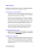
Registry Keys The registry key values are stored under HKEY_LOCAL_MACHINE\HARDWARE\DESCRIPTION\J2Health. Below is an example of the key values. Registry keys that are followed with the letters MAX or MIN are the J2 recommended maximum or minimum value for the registry key with the same name. Some values may only have a maximum or minimum value like Voltage Battery, Temperature CPU because values at the other extreme no relevant meaning.
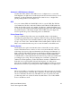
Refresh Interval The refresh interval controls how often the hardware monitor values are updated. This value can be set in the Health Monitor program window. Touch the area of the screen showing the current value and a touch keypad will pop up to allow you to change the interval as shown below. The value can also be changed by modifying the registry key: HKEY_LOCAL_MACHINE\HARDWARE\DESCRIPTION\J2Health\interval. The value is the number of seconds between updates. The default value is 5 seconds.
RAID RAID Overview The 650 is unique in that it is the only integrated POS computer to currently implement an integrated RAID function. The 650 uses the Intel Matrix Storage Technology to allow the two internal 2.5 inch hard drives to be configured as a RAID array. The 650 supports RAID 0, RAID 1 and Intel Matrix RAID which combines the benefits of two RAID volumes in a single RAID array. If you are not currently familiar with RAID arrays Intel has a good white paper on the subject at: http://www.intel.
Enabling RAID in the BIOS The Intel manual for the Intel Matrix Storage Manager covers this same information given below in more detail and can be downloaded from the J2 web site. The documentation below is tailored for the 650 only. Link: http://www.j2retailsystems.com/support/650/RAID/ Perform the following steps to enable the RAID option in the system BIOS: 1. Enter the BIOS Setup program by pressing the DEL key after the BIOS sign-on screen appears. 2.
Perform the following steps to install the Intel Matrix Storage Manager driver during operating system setup: 1. Press the F6 key when prompted in the status line with the Press F6 if you need to install a third party SCSI or RAID driver message. This message appears at the beginning of Windows XP setup (during text-mode phase). Note: Nothing will happen immediately after pressing F6. Setup will temporarily continue loading drivers.
If a hot spare is available, all that needs to be done is to swap the bad drive with the hot spare. Be sure to change the correct drive. SATA Ports 0 corresponds to the HDD 0, the top drive in the HDD bay and SATA Ports 1 corresponds to the HDD 1, the bottom drive in the HDD bay. Power to the system does not need to be turned off, and the system will still operate. First remove the bad drive. After removing the bad drive insert the hot spare into the 650.
The RAID will now rebuild an image of the good drive to the hot spare. Rebuilding Rebuilt The RAID has now mirrored the drive and the system is now protected for a drive failure. Note: Please refer to J2’s “Using RAID in a Point of Sale Environment” white paper for more information on using the 650 RAID function. (Available September 2008) 650 System Manual (Draft) Version 0.
Packing List In addition to the foam packing inserts, the following contents should be found in the 650 shipping carton. Standard Items 1: System with Power Supply and AC cord 2: Accessory kit 3: Cable Well cover 4: Hard Drive Mount Tray for 2nd Drive 5: Wall Mount/VESA bracket and Screws 6: WiFi option Mounting bracket / Screws 7: Printer Power Port Cable 8: COM Port Colored Coded Cable Labels 650 System Manual (Draft) Version 0.
0 Optional Peripherals MSR Overview The 650 can be ordered with a 3 track MSR. The MSR mounts on the right side of the 650 and uses a front facing MSR slot. This allows the 650 unit to be placed side by side, or in tight spaces, and still be able to swipe the card. The MSR appears to the software as a wedge type MSR with all data from the MSR being sent to the keyboard port. The MSR firmware and MSR settings can be changed and updated using the J2 MSR utility without removing the MSR from the unit.
Installing the 650 MSR The 650 MSR is installed by first removing the MSR cover plate on the right back side of the unit. Remove the two screws, as shown. Remove MSR cover plate Two small plastic hole covers need to be removed, as shown. Remove plastic hole covers Connect the two cable pairs together as shown. 650 System Manual (Draft) Version 0.
Slide the MSR in to its mounting groove being sure not to pinch the cable. Attach the MSR using the two screws at the locations, shown below. Mounting MSR 650 System Manual (Draft) Version 0.
You may now power up the 650 and the MSR should be working. For a quick test you can open Notepad and swipe a card, the information should appear in Notepad. You can now run the J2 MSR utility if you need any custom settings for the MSR. J2 650 MSR Utility The 650 MSR configuration utility can be downloaded from the J2 web site at http://www.j2retailsystems.com/support/650/. You may run the MSR utility from any folder you like.
Beep on Error: This setting will disable or enable the MSR double beep tone on a bad read. No data is output on a bad read. Inter-Character Delay: This sets the delay between characters sent by the MSR. The delay is set in milliseconds. Track Settings: Enable or disable the sending of track data, sentinels and LRC here. Advanced Settings Preamble and Postambles can be added here, in addition to track separators and end of data terminator. 650 System Manual (Draft) Version 0.
Data may be entered using the touch screen keypad or keyboard. Valid characters are any printable character and all control characters. Alphanumeric touch keyboard Control Key entry touch keyboard 650 System Manual (Draft) Version 0.
MSR Firmware Update The MSR firmware can be updated in-circuit using this utility. This is to allow options and features to be added to the MSR as required. 650 System Manual (Draft) Version 0.
650 UPS Specifications Batteries Run Time Power In Power Out Data Interface Batteries Type Battery Life Charge Time Charger Type Software Size 2 Hours for the standard 650. Run time will vary depending on the processor used and application load 19 Volts DC 13-16.8 Volts DC, 7.2 amps maximum RS232 DB9 connector 2 – 4 18650 cell Li-Ion pack with protection circuit 300 full discharge cycles 3 hours Smart Microcontroller based XP Standard Generic UPS driver / J2 Smart UPS driver 6” x 3.1” x 1.
Software Setup in XP 1: From the START button run CONTROL PANEL. 2: Double click POWER OPTIONS. 3: Select the UPS tab and click on Select under Details. 4: Under Select manufacturer select Generic. Select the COM port you wish to use in the On port drop down menu. Be sure this port is not used for anything else (printer) or the driver will not install. Select model should be Custom. Click Next>. 650 System Manual (Draft) Version 0.
5: The default values for the Interface Configuration are what the J2 UPS uses so just click Finish. 6: When returned to the Power Options Properties window click Apply to save the configuration. It will take a number of second to configure. Once done the Details should show Manufacture: Generic and Model: Custom and the UPS and driver should be working. This can be quickly tested by removing the AC power to the unit. If everything is working the Current power source: should change to On Battery.
STATUS LED There is one green status LED on the UPS. This can be viewed when by looking into the top of the base as shown in the picture below. Picture to be added here The status LED can be used to determine what mode the UPS is running in. Please refer to the following table.
Customer Display To be added Secondary Video Display To be added Fingerprint Reader / MSR To be added 650 System Manual (Draft) Version 0.
iButton / MSR To be added RFID / MSR To be added Laser Scanner To be added 650 System Manual (Draft) Version 0.
Contact Information Worldwide Headquarters: J2 Retail Systems Ltd. J2 House Clayton Road, Birchwood Warrington WA3 6RP United Kingdom 44 (0) 1925 817003 Phone 44 (0) 1925 811989 Fax info@j2retailsystems.com USA Headquarters: J2 Retail Systems, Inc. 2691 Dow Ave., Building A Tustin, CA 92780 USA (714) 669-3111 Phone (714) 669-3133 Fax info@j2retailsystemsusa.com 650 System Manual (Draft) Version 0.