USER'S MANUAL Of Intel X58 Express Chipset And Intel ICH10R Chipset Based M/B for Intel Core i7 Processors NO. G03-BI600 -F Rev: 2.0 Release date: April, 2009 Trademark: * Specifications and Information contained in this documentation are furnished for information use only, and are subject to change at any time without notice, and should not be construed as a commitment by manufacturer.
Environmental Protection Announcement Do not dispose this electronic device into the trash while discarding. To minimize pollution and ensure environment protection of mother earth, please recycle.
TABLE OF CONTENT SAFETY ENVIROMENTAL INSTRUCTION ....................................................................iii USER’S NOTICE.....................................................................................................................iv MANUAL REVISION INFORMATION ..............................................................................iv COOLING SOLUTIONS ........................................................................................................
-12 G.P.I.FUNCTION LED DISPLAY ...................................................................................... 48 Safety Environmental Instruction z Avoid the dusty, humidity and temperature extremes. Do not place the product in any area where it may become wet. z 0 to 40 centigrade is the suitable temperature.
USER’S NOTICE COPYRIGHT OF THIS MANUAL BELONGS TO THE MANUFACTURER. NO PART OF THIS MANUAL, INCLUDING THE PRODUCTS AND SOFTWARES DESCRIBED IN IT MAY BE REPRODUCED, TRANSMITTED OR TRANSLATED INTO ANY LANGUAGE IN ANY FORM OR BY ANY MEANS WITHOUT WRITTEN PERMISSION OF THE MANUFACTURER. THIS MANUAL CONTAINS ALL INFORMATION REQUIRED FOR THE UTILIZATION OF X58 EXPRESS INTEL EDITION MOTHER-BOARDS TO MEET THE USER’S REQUIREMENTS. BUT IT WILL CHANGE, CORRECT AT ANY TIME WITHOUT NOTICE.
Chapter 1 Introduction of X58 Express and ICH10R chipset based Motherboards 1-1 Features of Motherboard The X58 Express and ICH10R chipset based motherboard series are based on Intel X58 Express chipset and ICH10R chipsets technology which supports the innovative Intel® Core™ i7-965 processor Extreme Edition, Intel® Core™ i7-940 processors and Intel® Core™ i7-920 processors with QPI up to 6.4 GT/s.
ways. But please be caution that the over-clocking may cause the failure in system reliability. This motherboard provides the guaranteed performance and meets the demands of the next generation computing. But if you insist to gain more system performance with variety possibilities of the components you choose, please be careful and make sure to read the detailed descriptions of these value added product features, please get them in the coming section. 1-1.
G.P.I. Function—(Green power indicator function) The full name of G.P.I technology is Green Power Indicator technology, obviously technology utilized to low power consumption. G.P.I is a technology with remarkable power saving function. DIY Clear The CMOS Button is to facilitate the clear COMS process for power user overclocking function. The user can easily clear or restore COMS settings by pressing down the button, without taking trouble to remove the case and locate the jumper for clear CMOS.
1-2 Specification Spec Design Chipset CPU Socket LGA 1366 Memory Sockets Expansion Slots Description ∗ ∗ ∗ ∗ ∗ ∗ ∗ ∗ ATX form factor 6 layers PCB size: 30.5x24.5cm Intel X58 Express Chipset Intel ICH10R chipset Supports the Intel® Core™ i7-965 processor Extreme Edition, Intel® Core™ i7-940 processors and Intel® Core™ i7-920 processors. Support QPI up to 6.4 GT/s DDR3 Module sockets x 6, Support 6 pcs DDR3 1600 /DDR3 1333MHz/ DDR3 1066 memory modules expandable to 24GB.
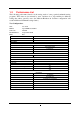
1-3 Performance List The following performance data list is the testing result of some popular benchmark testing programs. These data are just referred by users, and there is no responsibility for different testing data values gotten by users (the different Hardware & Software configuration will result in different benchmark testing results.
1-4 Layout Diagram Line IN (Blue) RJ-45 Ports ESATA Connectors CEN/BASS (Black) Line OUT (Green) Surrback (Orange) PS/2Mouse (Green) PS/2 Keyboard CMOS2 (Purple) Surround SPDIF-OUT1 (Gray) MIC-IN (Pink) USB connectors KB/MS Power On Jumper (JP1) PS2 KB/Mouse Port ATX 12V Power Conn. Coaxial S/PDIF out.
Jumpers Jumper JBAT JP1 JP3/JP4 Name CMOS RAM Clear Keyboard Power On Enabled/Disabled USB Power On Enabled/Disabled Connectors Connector ATXPWR1 ATX12V1 KB1 USB from CN1,CN2 and UL1, UL2 RJ45 LAN from UL1,UL2 AUDIO1 FLOPPY1 IDE1 DSATA1,DSATA2, DSATA3 E-SATA from CN1,CN2 SPDIF_ Out1 Headers Header FP_AUDIO1 USB1,USB2 SPEAK PWR LED JW_FP(PWR LED/Reset/ HD LED/PWR BTN) CPUFAN1 SYSFAN1, SYSFAN2 CDIN1 IR1 COM1 HDMI-SPDIF1 Expansion Sockets Socket/Slot LGA 1366 Socket DIMM_A2/DIMM_A1/ DIMM_B2/DIMM_B1/ DIMM_C2/
Chapter 2 Hardware Installation WARNING! 2-1 Turn off your power when adding or removing expansion cards or other system components. Failure to do so may cause severe damage to both your motherboard and expansion cards. Hardware installation Steps Before using your computer, you had better complete the following steps: 1. Check motherboard jumper setting 2. Install CPU and Fan 3. Install System Memory (DIMM) 4. Install Expansion cards 5. Connect IDE Front Panel /Back Panel cable 6.
(2) Keyboard function Enabled/Disabled: JP1 JP1 JP1 2-3 Closed KB Power ON Enabled 1-2 Closed KB Power ON Disable (Default) Keyboard/Mouse Power On Setting (3) USB Power On function Enabled/Disabled: JP3/JP4 JP3 / JP4 1-2 closed (Default) JP3 / JP4 USB Power On Disable 2-3 closed USB Power On Enabled USB Power-On Setting 2-3 Installing CPU 2-3-1 Glossary Chipset (or core logic) - two or more integrated circuits which control the interfaces between the system processor, RAM, I/O devises, and ad
Processor - the "central processing unit" (CPU); the principal integrated circuit used for doing the "computing" in "personal computer" Front Side Bus Frequency - the working frequency of the motherboard, which is generated by the clock generator for CPU, DRAM and PCI BUS. CPU L2 Cache - the flash memory inside the CPU, normal it depend on CPU type. 2-3-2 About Intel LGA 1366 CPU This motherboard provides a 1366-pin DIP, LGA 1366 Land Grid Array socket, referred to as the LGA 1366 socket.
2-3-3 1. LGA 1366 CPU Installation Guide Please make sure that CPU socket is facing towards 2. you and the level is on you left hand side. 3. Pick up the lode plate upwards about 100 degree to 4. Press down the level and move iit to the left side to make sure it is freed from the hook and then open it upwards about 135 degree. Remove the plastic protective cap from the socket. ( Put it to the original place if CPU is not installed . Do make sure it is moved upwards.
Alignment Key Alignment Key Pin-1 Indicator 5. Make sire that golden finger is on the left-down side as shown and match the two alignment keys on the CPU with two points of the socket. CPU can only be correctly installed with this direction. Incorrect installation might cause damage to CPU . 6.Put down the load plate. 7. Press down the load level and move it rightwards make sure it is locked under the notch.
2-3-4 Intel Reference Thermal Solution Assembly Align the fastener with the hole 1. Put the heat sink vertically above the CP-installed 2. Revolve the four fasteners in the counter-clockwise socket and make sure to align the four fasteners with four holes around the socket. direction. Motherboard 3. Press down two fasteners down in the oblique crossing 4. direction as shown above. Turn over the motherboard carefully to make sure the fastener insert in the right direction.
2-4 Installing Memory This motherboard provides six 240-pin DDR3 DUAL INLINE MEMORY MODULES (DIMM) socket for DDR3 memory modules capacity expansion to maximum memory volume of 24 GB.
2-5 Expansion Cards 2-5-1 Procedure For Expansion Card Installation 1. Read the documentation for your expansion card and make any necessary hardware or software setting for your expansion card such as jumpers. 2. Remove your computer’s cover and the bracket plate on the slot you intend to use. 3. Align the card’s connectors and press firmly. 4. Secure the card on the slot with the screen you remove above. 5. Replace the computer system’s cover. 6. Set up the BIOS if necessary. 7.
2-5-3 PCI Express Slot The X58 Express chipset based motherboard series offer four PCI-Express2.0 x16 graphics slots with PE1 and PE4 being PCI Express 2.0 x16@16 lane slots while PE3 and PE5 being PCI Express 2.0 x16@ 8 lane slots. These four graphics slots are fully compatible with the latest AMD CrossFireX Technology to guarantee the fully operational Multi-GPUs graphics function and avoid the possible installation error.
2-5-4 Installing the CrossFire Bridge Card The following illustrations show you how to install the CrossFire Bridge Card. Bridge for CrossFire Tech. Supported VGA Cards In order to activate the CrossFire technology, you have to install the optional Bridge for your CrossFire Tech. Supported VGA Cards before you activating the advance multi-GPUs functions. For CrissFire Bridge installation 1. Install your CrossFire Tech Supported VGA Cards in the PCI-E x16 slots. 2.
Notice! The motherboard and graphics card in the illustration is for reference use only; We suggest that you install graphics cards in PE1 and PE4 slot for better CrossFire performance; We suggest that you install graphics cards in PE1,PE3 and PE4 slots for better performance when installing 3 graphics card.
2-6 Connectors, Headers 2-6-1 Connectors (1) Power Connector (24-pin block): ATXPWR1 ATX Power Supply connector: This is a new defined 24-pins connector that usually comes with ATX case. The ATX Power Supply allows using soft power on momentary switch that connect from the front panel switch to 2-pins Power On jumper pole on the motherboard.
Pin 1 (3) PS/2 Mouse & PS/2 Keyboard Connector: KB1 The connectors are for PS/2 keyboard and PS/2 Mouse input devices. (4) USB Port connector: USB port from CN1, CN2 and UL1, UL2 The connectors are 4-pin connectors that connect USB devices with the 400Mbit / sec data transfer rate to the system board. (5) LAN Port connector: RJ-45 LAN port from UL1, UL2 This connector is standard RJ45 over USB connectors for Network connection.
Pin 1 FLOPPY (Black) Floppy Drive Connector (8) IDE Connector (40-pin block): IDE1 This connector supports the provided IDE hard disk ribbon cable. After connecting the single plug end to motherboard, connect the two plugs at other end to your hard disk(s). If you install two hard disks, you must configure the second drive to Slave mode. IDE1 Pin 1 Primary IDE Connector(Black) • Two hard disks can be connected to each connector.
(10) ESATA Port: ESATA ports from CN1, CN2 These two connectors support the External Serial ATA2 (eSATA) to enable the full SATA interface speed outside the chassis. (11) SPDIF Out connectors: SPDIF_Out1 The SPDIF output is capable of providing digital audio to external speakers or compressed AC3 data to an external Dolby digital decoder. Use this feature only when your stereo system has digital input function.
JW FP PWRBTN GND PWRBTN PWRLED Pin 1 PWRLED VCC5 PWR LED rebooting in order to prolong the lift of the system’s power supply. See the figure below. (7) Power switch: PWR BTN This 2-pin connector connects to the case-mounted power switch to power ON/OFF the system. SPEAK VCC5 HDDLE GND RSTSW NC HDLED RESET GND VCC5 Pin 1 SPKR NC Pin 1 System Case Connections (8) FAN Headers: SYSFAN1, SYSFAN2 (3-pin), CPUFAN1 (4-pin) These connectors support cooling fans of 350mA (4.
GND IR +5VX (10) IR infrared module Headers (5-pin): IR1 This connector supports the optional wireless transmitting and receiving infrared module. You must configure the setting through the BIOS setup to use the IR function. 2 6 5 IRRX GND IRTX Pin 1 IR infrared module Headers (11) Serial COM Port header: COM1 COM1 is a 9-pin RS232 connector.
2-7 Starting Up Your Computer 1. After all connection is made, close your computer case cover. 2. Be sure all the switch are off, and check that the power supply input voltage is set to proper position, usually in-put voltage is 220V∼240V or 110V∼120V depending on your country’s voltage used. 3. Connect the power supply cord into the power supply located on the back of your system case according to your system user’s manual. 4. Turn on your peripheral as following order: a. Your monitor. b.
Chapter 3 Introducing BIOS The BIOS is a program located on a Flash Memory on the motherboard. This program is a bridge between motherboard and operating system. When you start the computer, the BIOS program will gain control. The BIOS first operates an auto-diagnostic test called POST (power on self test) for all the necessary hardware, it detects the entire hardware device and configures the parameters of the hardware synchronization.
3-3 The Main Menu Once you enter AMI BIOS Setup Utility, the Main Menu (Figure 3-1) will appear on the screen. The Main Menu allows you to select from 12 setup functions and 2 exit choices. Use arrow keys to select among the items and press to accept or enter the sub-menu. CMOS Setup Utility-Copyright(C)1985-2005 American Megatrends. Inc.
Load Optimized Defaults Use this menu to load the BIOS default values these are setting for optimal performances system operations for performance use. Load Failsafe Defaults This menu uses a minimal performance setting, but the system would run in a stable way. Save Changes and Exit Save CMOS value changes to CMOS and exit setup. Discard Changes and Exit Abandon all CMOS value changes and exit setup. 3-4 Standard BIOS Features The items in Standard CMOS Setup Menu are divided into several categories.
DMA MODE: the optional settings are Auto, SWDMAn, MWDMAn , UDMAn. This option allows you to enable the HDD S.M.A.R.T Capability S.M.A.R.T.: (Self-Monitoring, Analysis and Reporting Technology). The optional settings are Auto; Disabled; and ENABLED. 32 Bit Data Transfer: the optional settings are: Disabled and Enabled. Floppy A This item is for specific floppy disk drive settings. Select according to the specification of the floppy disk you use.
3-6 Advanced Chipset Features The Advanced Chipset Features Setup option is used to change the values of the chipset registers. These registers control most of the system options in the computer. CMOS Setup Utility-Copyright(C)1985-2005 American Megatrends. Inc.
Hard Disk Write Protection Use this item to enable or disable hard disk write protection. This will be effective ony if the device is accessed through BIOS. IDE Detect Time Out(Sec) Select the time out value for detecting ATA/ATA(PI) devices. ATA(PI) 80 Pin Cable Detect( Host & Device; Host; Device) Select the mechanism for detecting 80 pin ATA(PI) cable 3-7-2 Onboard Device Control CMOS Setup Utility-Copyright(C)1985-2005 American Megatrends. Inc.
Set it as enabled if you wish to resume the system by keyboard. The optional setting is : Enabled; Disabled. Power On by Mouse Set it as enabled if you wish to resume the system by mouse. The optional setting is : Enabled; Disabled. Serial Port1 /Port 2 Address Use this item to select serial port address for serial port one. Serial Port2 Mode The optional settings are: Normal; IrDA (1.6 ns); IrDA(3/16 bit). PWRON After PWR-Fail The optional settings are: Always On; Always Off and Former-Sts.
3-8 Power Management Features The Power Management Setup allows you to configure your system to most effectively save energy saving while operating in a manner consistent with your own style of computer use. CMOS Setup Utility-Copyright(C)1985-2005 American Megatrends. Inc.
3-9 Miscellaneous Control CMOS Setup Utility-Copyright(C)1985-2005 American Megatrends. Inc.
3-10 PC Health Status This section shows the Status of you CPU, Fan, and Warning for overall system status. is only available if there is Hardware Monitor onboard. This CMOS Setup Utility-Copyright(C)1985-2005 American Megatrends. Inc. PC Health Status Help Item PC Health Status Smart FAN Configuration H/W Health Function Press Enter Enabled CPU Temperature: System Temperature: CPUFAN Speed: SYSFAN1 Speed: SYSFAN Speed: Vcore NB1.1V : +5V +12V 5VSB VDIMM : 50°C/122°F 60°C/140°F 2923RPM N/A N/A 1.
3-11 Power User Overclock Setting CMOS Setup Utility-Copyright(C)1985-2005 American Megatrends. Inc. Power User Overclock Setting Help Item Overclocking Configuration CPU Bridge Configuration Press Enter CPU Overclock Configure CPU Bridge Feature 133 CPU Voltage at next boot Default VDIMM Select Default NB1.
Type the password, up to eight characters in length, and press . The password typed now will clear any previously entered password from CMOS memory. You will be asked to confirm the password. Type the password again and press . You may also press to abort the selection and not enter a password. To disable a password, just press when you are prompted to enter the password. A message will confirm that the password will be disabled.
Chapter 4 DRIVER & FREE PROGRAM INSTALLATION Check your package and there is A MAGIC INSTALL CD included. This CD consists of all DRIVERS you need and some free application programs and utility programs. In addition, this CD also include an auto detect software which can tell you which hardware is installed, and which DRIVERS needed so that your system can function properly. We call this auto detect software MAGIC INSTALL.
4-1 INF Install Intel X58 Chipset System Driver 1.Click INF item when Magic Install menu 2.Click Next when Intel Chipset Device Software appears. appears. 3. Click Yes on the Licence Agreement. 4 . After reading the Readme File Information click Next. 5.Click Finish to finish installation.
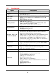
4-2 SOUND Install ALC888 HD Audio Codec Driver 1.Click Sound on the Magic Install menu. 2 . lick NEXT When Realtek High Definition Audio driver windows appear 3. Click FINISH and restart your computer 4. Manual Sound Effect Setting 5. The mixer. 6. Audio input and output settings. 7. Microphone effect. 8 3D sound effect..
NOTE: Please upgrade your Windows XP to Service Pack 2 / Windows 2000 to Service Pack 4 or later before you the HD Audio CODEC driver. 4-3 LAN Install Realtek Gigabit Ethernet NIC Driver 1. Click LAN when Magic Install Menu appears 2. Click NEXT, install REALTEK LAN and Fast Ethernet NIC Driver 3. Click install to begin the installation. 4. After driver installation completed, Click Finish. 4-4 RAID Install JMICRON RAID Driver 1. Click RAID when MAGIC INSTALL MENU 2.
3.To select the setup type that best suits your need 4. Click the “Install” to begin the installation. 1. Choose whether you would like to restart your computer and then Click FINISH to complete the installation. 4-5 Norton Install Norton Internet Security 2009 1. Click Norton when Magic Install menu 2. Click AGREE & INSTALL after reading Unser appears. License Agreement.
4-6 PC-HEALTH Install MyGuard Hardware Monitor Utility 1. Click PC-HEALTH when MAGIC INSTALL 2. Click Next when Install shield wizard Window MENU appears appears. 3. Click Install to begin the installation. 4-7 RAIDDISK 4. Click Finish to complete the installation. Install JMICRON X32 RAID Disk 1. Click PC-CILLIN when MAGIC INSTALL 2.
4-8 AHCI Install Intel AHCI Driver If you want to use Intel SATA AHCI mode for your system , please according to following step install driver : 1. Copy CD:\Intel3x_4x\ICH10_AHCI\f6flpy32 all file to empty floppy disk root directory . (for windows 2000 / xp / vistaX32) Copy CD:\Intel3x_4x\ICH10_AHCI\f6flpy64 all file to empty floppy disk root directory . (for windows xp64 / vistaX64) 2. Please going to BIOS setup \ Integrated Peripherals \ Onboard SATA Function , Set the SATA mode to “AHCI” 3.
4-9 How to Update BIOS Before updating the BIOS, users have to check if the “Miscellaneous Control” of BIOS SETUP has the “Flash Part Write Protect” selection. If there is one, users have to “Disable” the “Flash Part Write Protect” selection of the “Miscellaneous Control” in BIOS SETUP. Otherwise the system the will not allow you to upgrade BIOS by Award Flash Utility. If there is no such selection, users can follow the 4 steps directly to update BIOS. STEP 1. Prepare a boot disc.
category on the right window. Choose Create RAID Disk Drive and press Enter, then the following windows will show up: Press Enter to the Level item, then select RAID mode by navigation keys [↑↓]: Then press Enter to enter the Confirm Creation item, then dialogue box would show Create RAID on the select HDD(Y/N)?Y. Type Y, and press Enter, the following window would show up to confirm the success in creating RAID mode. Step3.
Installation of Windows XP/ Windows 2000/Vista For installation of Windows XP or Windows 2000, please insert Windows XP, Windows 2000 CD or Vista into the CD-ROM drive. Then remove the floppy diskette, and boot the system. At the very beginning, you will see the message at the bottom of screen, “Press F6 if you need to install a third party SCSI or RAID driver….” At this moment, please press key and follow the instructions of Windows XP/2000/Vista for the proper installation.
NOTE: Functions of each version will differ from each other, and will be based on the function descriptions of each version.