User’s Manual Intel i945P / i945PL mainboard for Intel Soc ket 775 pr ocessor processor Sock TRADEMARK All products and company names are trademarks or registered trademarks of their respective holders. These specifications are subject to change without notice. 6000002594510 Manual Revision 1.
DISCLAIMER OF WARRANTIES: THERE ARE NO WARRANTIES WHICH EXTEND BEYOND THE DESCRIPTION ON THE FACE OF THE MANUFACTURER LIMITED WARRANTY. THE MANUFACTURER EXPRESSLY EXCLUDES ALL OTHER WARRANTIES, EXPRESS OR IMPLIED, REGARDING ITS PRODUCTS; INCLUDING ANY IMPLIED WARRANTIES OF MERCHANTABILITY, FITNESS FOR A PARTICULAR PURPOSE OR NONINFRINGEMENT.
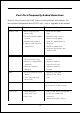
Post Port Frequently Asked Questions Below is a list of some basic POST Codes, possible problems and solutions. For more detailed information about POST Codes, refer to Appendix in this manual. P O ST C O D E P r o bl e m So l uti o n FFh o r CFh 1 .B IO S c hip inse rte d 1 . Re inse rt the B IO S inc o rre c tly c hip 2 . Inc o rre c t BIO S update ve rsio n 3 . M ainbo ard pro ble m 4 . Add-o n c ard inse rte d inc o rre c tly. 2 .
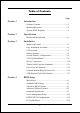
Table of Contents Page Section 1 Introduction Package Contents ...................................................... 1- 1 Mainboard Features ................................................... 1- 2 System Block Diagram ............................................. 1-5 Section 2 Specification Mainboard Specification ............................................ 2- 1 Section 3 Installation Mainboard Layout ..................................................... 3- 1 Easy Installation Procedure ...........
Power BIOS Features ................................................ 4-19 Defaults Menu ........................................................... 4-22 Supervisor/User Password Setting ............................ 4- 23 Exit Selecting .............................................................. 4- 24 Section 5 Driver Installation Easy Driver Installation ............................................. 5-1 Realtek Sound Manager Quick User guide ...............
Page Left Blank vi
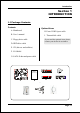
Introduction Section 1 INTRODUCTION 1-1 Package Contents Contents Optional Items A. Mainboard H. Extra USB2.0 port cable B. User’s manual I. ThermoStick cable C. Floppy drive cable If you need the optional item, please contact your dealer for assistance. D. HDD drive cable E. CD (drivers and utilities) F. I/O Shield G.
Introduction 1-2 Mainboard Features Brief Introduction Intel® Pentium® 4 processors The Pentium 4 processor is designed to deliver performance across applications and usages where end-users can truly appreciate and experience the performance. The Pentium 4 processor delivers this world-class performance for consumer enthusiasts and business professional desktop PC users as well as for entry-level workstation users.
Introduction Ultra ATA100 The mainboard provides an Ultra ATA100 Bus Master IDE controller. This controller supports Ultra ATA100 protocols which are ideal to support demanding applications such as real-time video, multimedia, and a high performance operating system. A new IDE cable is required for Ultra ATA100. Hardware Monitoring Hardware monitoring enables you to monitor various aspects of the system operation and status. This includes CPU temperature, voltage and fan speed in RPMs.
Introduction Special Features BIOS Features: & Magic Health Reports your system hardware status for every boot-up to help detect faults early. Monitor hardware status including CPU temperature, CPU/Memory/ Chipset voltage, fan RPM speed for chassis fan, CPU fan & Power supply fan. & EZ-Boot Simply press “ESC” to select your bootable device. No more hassle to search the BIOS menu, change and re-start. & PowerBIOS Supporting a full range of overclocking setting via BIOS.
Introduction 1-3 System Block Diagram Page 1-5
Introduction Page 1-6
Specification Section 2 SPECIFICATION Mainboard Specification Processor ® ® ® ® Socket LGA775 for Intel Celeron D 3xx series, Intel Pentium 4 5xx/ 6xx series, P4EE up to 3.
Specification IDE One IDE interface (up to 2 IDE devices) with UDMA-33, ATA-66/100 support from embedded IDE controller USB Eight USB connectors compliant with USB2.
Specification BIOS Flash EEPROM with Award Plug&Play BIOS Support ACPI S3 (Suspend To RAM) mode in ACPI compliant O/S Support EZ Boot for fast bootable device selection Support Magic Health for system hardware status report during system boot-up Peripheral Interfaces ) At Rear Panel PS/2 keyboard and mouse ports One Parallel (printer) port One S/PDIF-Out Coaxial jack One Serial port One RJ45 LAN connector Four USB2.
Specification Special Features Support KBPO function – Keyboard power on, turn on the computer from keyboard Support Wake-On-LAN by PME Support USB resume in S3 Onboard Post Port LED display for system debugging Support Asynchronous clocking mode between FSB and PCI/PCI-E PowerBIOS for excellent overclocking features: - Programmable FSB and PCI Clock output frequency with 1MHz fine tuning - Support BIOS adjustable CPU multiplier, FSB clock, PCI-E x16 clock, DIMM frequency - Support BIOS adjustab
Installation Section 3 INSTALLATION Mainboard Layout Note: Depending on the model you purchased, some components are optional and may not be available.
Installation Easy Installation Procedure The following must be completed before powering on your new system: 3-1. CPU Installation 3-2. Jumper Settings 3-3. System Memory 3-4. VGA card installation 3-5. Device Connectors 3-1 CPU Installation 1 2 Step 1 Step 2 Open load plate ( A ) , DO NOT touch socket contacts ( B ). Remove protective cover ( C ) from load plate. Please do not discard the protective cover.
Installation 3 4 Step 3 Step 4 Remove the processor from the protective cover. Do not touch the bottom of the processor. The processor cover should not be discarded. Always replace the processor cover if the processor is removed from the socket. Hold the processor with thumb and index fingers as shown. Ensure fingers align to the socket cutouts ( D ) , processor notches ( E ) align to socket convexes ( F ).
Installation 3-2 Jumper Settings JPCIE1 JPCIE2 JCMOS JUSB JCMOS: Clear CMOS data Jumper If the CMOS data becomes corrupted or you forgot the supervisor or user password, clear the CMOS data to reconfigure the system back to the default values stored in the ROM BIOS. 1 Settings: 1-2: Normal (Default) 2-3: Clear CMOS JUSB: USB S3 Wake up Jumper This jumper disconnects 5V standby voltage to USB devices.
Installation JPCIE1~JPCIE2:PCI-E slot Control Jumper These jumpers redirect the PCI-E signals from PCI-EXP2 and PCI-EXP3 to the PCI-EXP4 connector. This allows 4x bandwidth on PCI-EXP4 slot to cater for higher bandwidth cards such as VGA and RAID connectors. JPCIE1 JPCIE2 Settings: 1-2: PCI-E x4 mode (Default) 2-3: PCI-E x1 mode Set both jumpers to 1-2 to use PCI-EXP4 as high bandwidth PCI-E x4 slot. Set both jumpers to 2-3 to use PCI-EXP2 and PCI-EXP3 slots.
Installation 3-3 System Memory Configuration The mainboard accommodates four 240-pin DDR2 DIMM sockets. • Supports up to 4GB of 400/533/667MHz DDR2 SDRAM (2GB and 400/ 533MHz for i945PL chipset support only). • Supports dual channel memory interface. • Supports non-ECC memory and non-Registered DIMMs only. • SPD (Serial Presence Detect) scheme for DIMM detection support. • Supports configurations defined in the JEDEC DDR2 DIMM specification only.
Installation Memory configurations supported: (Optional) 1 DIMM (64-bit) DIMM#1 DIMM#2 2 DIMM (128-bit) SS/DS SS/DS SS/DS DIMM#3 DIMM#4 SS/DS SS/DS SS/DS SS/DS SS/DS 3 DIMM (128-bit) 4 DIM M (128-bit) SS/DS SS/DS SS/DS SS/DS SS/DS SS/DS SS/DS SS/DS SS/DS SS/DS SS/DS SS/DS SS/DS SS/DS * SS: Single-Sided DIMM, DS: Double-Sided DIMM Note: Using non-compliant memory with higher bus speeds (overclocking) may severely compromise the integrity of the system.
Installation 3-4 VGA Card Installation Single VGA card Installation To install a single VGA card in Single Mode, insert the VGA into the "PCI-EXP1" VGA slot. (labeled on the board) When installing the VGA card, make sure the card edge connector is fully inserted into the slot and the clicker is locked properly. Dual VGA card Installation - GLI mode:(Graphics Link Interface) The mainboard is equipped with a secondary PCI-E VGA slot to support GLI mode technology.
Installation “PCI-EXP4” VGA slot operates at PCI-E x4 bandwidth, the following table of VGA cards have been tested compatible with this slot.
Installation 3-5 Device Connectors The I/O back panel for this mainboard is shown below. When installing the mainboard into the computer case, use the bundled I/O shield to protect this back panel. RJ45 LAN Parallel Port PS/2 Mouse PS/2 Keyboard S/PDIF-out Coaxial Jack COM USB2.0 x 4 ports 7.1 Audio Channel - I/O Ports JCPU_FAN JCPU_FAN / JPWR_FAN / JSYS_FAN: CPU/Power/Chassis Fan Power Connectors JCPU_FAN: The CPU must be kept cool by using a heatsink with fan assembly.
Installation FDD: Floppy Controller Connector This connects to the floppy disk drive. IDE1: ATA-66/100 IDE Connector IDE1 FDD 34 33 1 2 FDD 40 39 This mainboard is equipped with 1 IDE connectors to support up to 2 ATA-100 IDE drives. It supports PIO and DMA mode operations for maximum data transfer rate of 100MB/sec per channel. When using two IDE drives on the same connector, one must be set to Master mode and the other to Slave mode. Refer to your disk drive user’s manual for details.
Installation CFPA: Front Panel Audio Connector This audio connector connects to the audio jacks located on the front panel. Refer to your case manual to match the pin-out names. Front Line-out-R NC NC MIC_In Front Line-out-L 9 1 2 10 NC NC GND Key +5V CD-IN: CD Audio_IN Connector The CD-IN connector is used to receive audio from a CD-ROM drive, TV tuner or MPEG card.
Installation CUSB3/CUSB4: Four USB 2.0 ports This mainboard includes additional USB2.0 ports, identified by 10-pin connector. If you wish to use the additional USB ports, install the card-edge bracket to the system chassis then insert its cables to this 10-pin connector. CUSB3 CUSB4 CAUTION ! If you purchased a separate USB cable make sure it has the same pin assignment. A different pin assignment may damage the system. If you need the USB cable, please contact our retailer.
Installation CFP: Front Panel Connector HD_LED This LED will light up whenever the hard drive is being accessed. PWR_LED This connects to the power button of the system chassis CFP RST This switch allows you to reboot without having to power off the system thus prolonging the life of the power supply or system. PW_ON This is connected to the power button on the case. To use the Soft-Off by PWR-BTTN feature, refer to the Power Management Setup in the BIOS setup section of this manual.
Installation k Function (Optional) 3-6 T her mo Stic Stick This mainboard is equipped with a digital thermometer capability to monitor any temperature. This is useful for measuring heat on peripherals such as VGA cards, hard disk drives, DIMMs or even on-board components such as chipset, MOSFETS, etc.
Installation 3-9 ACPI S3 (Suspend To RAM) Function This mainboard supports the STR (Suspend To RAM) power management scheme by maintaining the appropriate power states in the RAM interface signals. The power source to the RAM is kept active during STR (ACPI S3). Advanced Configuration Power Interface (ACPI) provides many Energy Saving Features for operating systems that support Instant ON and QuickStart TM function. 1. To enable STR functionality to save system power : a.
Installation 3-9 ACPI S3 (Suspend To RAM) Function This mainboard supports the STR (Suspend To RAM) power management scheme by maintaining the appropriate power states in the DDR SDRAM interface signals. The power source to the DDR SDRAM is kept active during STR (ACPI S3). Advanced Configuration Power Interface (ACPI) provides many Energy Saving Features for operating systems that support Instant ON and QuickStartTM function. 1. To enable STR functionality to save system power : a.
Installation Page 3-18
BIOS Section 4 BIOS SETUP Main Menu The ROM BIOS contains a built-in Setup program which allows user to modify the basic system configuration and hardware parameters. The modified data is stored in a battery-backed CMOS, so that data will be retained even when the power is turned off. In general, the information saved in the CMOS RAM will stay unchanged unless there is a configuration change in the system, such as hard drive replacement or a device is added.
BIOS The main menu displays all the major selection items. Select the item you need to reconfigure. The selection is made by moving the cursor (press any direction (arrow key ) to the item and pressing the ‘Enter’ key. An on-line help message is displayed at the bottom of the screen as the cursor is moved to various items which provides a better understanding of each function. When a selection is made, the menu of the selected item will appear so that the user can modify associated configuration parameters.
BIOS 4-2 Advanced BIOS Features Selecting the “ADVANCED BIOS FEATURES” option in the CMOS SETUP UTILITY menu allows users to change system related parameters in the displayed menu. This menu shows all of the manufacturer’s default values for the board. Pressing the [F1] key displays a help message for the selected item. Figure 3: BIOS Features Setup CPU Feature This field is available only for Pentium® CPU with Prescott core.
BIOS Hyper-Threading Technology Enables the CPU Hyper-Threading Technology. Options: Enables, Disabled. It is recommend to enable Hyper-Threading Technology on system with Windows XP and Linux 2.4 and disabling it for legacy OS. First /Second/Third/Other Boot Device The BIOS attempts to load the operating system from the devices in the sequence selected in these items. Options: Floppy, LS120, Hard Disk, CDROM, ZIP100, USB-FDD, USB-CDROM, LAN, Disabled.
BIOS functionality. APIC is an Intel chip that provides symmetric multiprocessing (SMP) for its Pentium systems. Options: Enabled, Disabled. HDD S.M.A.R.T. Capability The S.M.A.R.T. (Self-Monitoring, Analysis, and Reporting Technology) system is a diagnostics technology that monitors and predicts device performance. S.M.A.R.T. Software resides on both the disk drive and the host computer. If a device failure is predicted, the host software, through the Client WORKS S.M.A.R.
BIOS DRAM Timing Selectable For setting DRAM Timing, select By SPD to follow Intel PC DDR SDRAM Serial Presence Detect Specification. Options: Manual, By SPD. CAS Latency Time This item specifies the number of clock cycles needed after a Column Address Strobe (CAS) signal before data can be read. Options: 5, 4, 3, 6, Auto. DRAM RAS# to CAS# Delay This item sets the timing parameters for the system memory such as the CAS (Column Address Strobe) and RAS (Row Address Strobe). Options: 2, 3, 4, 5, 6, Auto.
BIOS 4-4 Integrated Peripherals Figure 5: Integrated Peripherals Realtek Lan Boot ROM Enable/disable the onboard Realtek Lan Boot ROM for booting from LAN. Options: Enabled, Disabled. PCI Express Function Scroll to PCI Express Function and press . The following screen appears: PCIEX-2 Slot / PCIEX-3 Slot / PCIEX-4 Slot PCI-E device disabled function. Options: Auto, Enabled, Disabled. PCI-E Compliancy Mode Allows you to select the PCI-E compliancy mode. Options: V1.0a, V1.0.
BIOS Chipset IDE Devices Scroll to Chipset IDE Devices and press . The following screen appears: Delay For HDD (Secs) This item allows you to set longer time stand by before system Scan HDD at post screen. Some HDD may need a longer stand by time before it can be detected. Options: 0 ~ 15. IDE HDD Block Mode IDE Block Mode allows the controller to access blocks of sectors rather than a single sector at a time. The default is Enabled. Options: Enabled, Disabled.
BIOS support Ultra DMA-33/66/100, select Auto to enable UDMA mode by BIOS. Options: Auto, Disabled. *** Chipest Serial ATA Setting *** Chipest Serial ATA This sets the mode of SATA. Combined mode will force SATA to replace one of the traditional IDE Primary or Secondary ports. Enhanced mode allows Serial ATA to work simultaneously with Parallel -ATA. Options: Disabled, Auto, Combined Mode, Enhanced Mode, SATA Only. SATA Port Speed Settings This item allows you to select Serial ATA port speed.
BIOS USB Keyboard Support Enable/Disable support for USB keyboard under DOS. Options: Auto, Enabled, Disabled. USB Mouse Support Enable/Disable support for USB mouse under DOS. Options: Enabled, Disabled. High Definition Audio (Intel® High Definition Audio Controller) This item allows you disable the on-chip Audio. Options: Auto, Disabled. Realtek Lan Device Onboard LAN device control function. Options: Auto, Enabled, Disabled. Legacy Devices Scroll to Legacy Devices and press .
BIOS Parallel Port Mode This field allows the user to select the parallel port mode. Options: SPP, EPP, ECP, ECP+EPP. EPP Mode Select This field allows the user to select the EPP mode for parallel port mode. Options: EPP1.9, EPP1.7. ECP Mode USE DMA This field allows the user to select DMA1 or DMA3 for the ECP mode. Options: DMA1, DMA3.
BIOS 4-5 Power Management Setup Choose the “POWER MANAGEMENT SETUP” in the CMOS SETUP UTILITY to display the following screen. This menu allows the user to modify the power management parameters and IRQ signals. In general, these parameters should not be changed unless it’s absolutely necessary. Figure 6: Power Management ACPI Suspend Type This item allows you to select S1(Power-On-Suspend) or S3(Suspend-To-RAM) function. When set to “S3(STR)” or “S1&S3” the following two fields become available.
BIOS PCI Express PME PCI-E device PME function. Options: Enabled, Disabled. Power Management Use this to select your Power Management selection. The default is User define. Max. saving: Maximum power savings. Inactivity period is 1 minute in each mode. Min. saving: Minimum power savings. Inactivity period is 1 hour in each mode. User define: Allows user to define PM Timers parameters to control power saving mode.
BIOS Wake-Up by PCI Card An input signal form PME on the PCI card awakens the system from S3 suspend state. Options: Enabled, Disabled. Power On by Ring When enabled, any modem activity awakens the system from soft-off state. Options: Enabled, Disabled. USB Wake-Up From S3 This item allows a USB device to wake-up the system from S3 suspend state. Options: Enabled, Disabled.
BIOS 4-6 PNP/PCI/PCI-E Configuration This page lets the user to modify the PCI/PCI-E IRQ signals when various PCI/ PCI-E cards are inserted. WARNING: Conflicting IRQ’s may cause system unable to locate certain devices. Figure 7: PNP/PCI Configuration Setup Resources Controlled By Determines what controls system PNP/PCI resources. The default is Auto (ESCD). Manual: PNP Card’s resources are controlled manually.
BIOS Interrupt requests are shared as shown below: INT A Audio V PCI 1 V PCI 2 INT B V V PCI-EXP3 (x1) V V Onboard LAN Onboard USB1 V V Onboard USB2 IMPORTANT! When using PCI cards on shared IRQ slots, make sure its drivers support “Shared IRQ”, or that the cards do not need IRQ assignments. IRQ conflicts between the two PCI groups will make the system unstable or cards inoperable. V Onboard USB3 V Onboard USB4 USB 2.
BIOS Current System/CPU Temperature Displays the current system/CPU temperature. Thermo Stick Temperature Displays the current thermo Stick temperature. Current CPU/Chassis/Power FAN Speed Displays the current speed of the CPU, chassis, and power fan speed in RPMs. VDimm The voltage level of the DRAM. Chipset Voltage The voltage level of chipset. Vcore The voltage level of the CPU (Vcore). +12V, VCC, 5VSB, 3VSB The voltage level of the switching power supply. VBAT The voltage level of the battery.
BIOS SmartFan Function Scroll to SmartFan Function and press . The following screen appears: Smart CPU FAN Function This item selects how the fan speed should be set. Full speed fixes fan speed at100% duty cycle. Control the Fan by Duty-Cycle directly. By Temperature calculates the fan speed according to different temperature range. To use By Temperature setting, refer to the example below to set the temperature and duty cycle.
BIOS 4-8 Power BIOS Features This page lets you adjust various parameters to obtain improved performance for overclocking. Warning: Overclocking requires expert knowledge and risks permanent damage to system components. We recommend you leave these parameters at their default values for proper operation.
BIOS CPU CLOCK/SPEED Enables you to increment the CPU’s clock generator at 1MHz step. This works together with CPU Clock Ratio (below) to set the CPU operating frequency. CPU Clock Generator x CPU Clock Ratio = CPU Frequency For example, if you have a processor that is rated at 2.4GHz and the clock generator is 200MHz, then 200MHz x 12 = 2.4GHz Press to display the following screen: (When FSB is 800/1066MHz) (When FSB is 533MHz) Key in the DEC (decimal) number for the CPU CLOCK/SPEED.
BIOS PCI Freq Sel Enables you to select the PCI Frequency. Options: Sync., 37.5MHz, 40MHz, 33.3MHz. System Memory Frequency Enables you to select a ratio of the DDR2 DRAM to match the installed DRAM frequency. We recommend that you leave this item at the default value. Options available depend on system FSB.
BIOS Chipset Voltage This item allows you to adjust the Chipset voltage. Options: -0.00V to +0.30V in 0.1V increments. We recommend that you leave this at the default value. VDIMM Voltage This item allows you to adjust the DIMM slot voltage. Options: +0.00V, +0.05V, +0.10V, +0.15V, +0.22V, +0.27V, +0.32V, +0.37V. We recommend that you leave this at the default value.
BIOS 4-10 Supervisor/User Password Setting This function lets you set either Supervisor or User Password, or both, to prevent unauthorized changes to BIOS menus. supervisor password: full rights to enter and change options of the setup menus. user password: only enter but no rights to change options of the setup menus. When you select this function, the following message will appear at the center of the screen to assist you in creating a password.
BIOS 4-11 Exiting BIOS Save & Exit Setup Pressing on this item asks for confirmation: Save to CMOS and EXIT (Y/N)? Y Pressing “Y” stores the selections made in the menus in CMOS – a special section of memory that stays on after you turn your system off. The next time you boot your computer, the BIOS configures your system according to the Setup selections stored in CMOS. After saving the values the system is restarted again.
Drivers Installation Section 5 DRIVER INSTALLATION Easy Driver Installation Once the operating system has been installed, you need to install the drivers for the mainboard. Please select: Method 1 Auto Installation Method 2 Manual Installation Please visit www.windowsupdate.com to update Windows XP before installing INTEL series driver >> INTEL CHIPSET INF FILES >> REALTEK LAN Driver >> REALTEK High Definition Audio Driver >> USB 2.
Drivers Installation Realtek Sound Manager Quick User-guide Introduction To obtain the best performance from your audio system, run the "Sound Manager" utility to adjust the settings to suit your needs. This section of the manual is intended to provide a quick user-guide to setup "Sound Manager". For more detailed information, refer to "Sound Manager manual" in the CD. 1. Right-click “Sound Effect” button on the task bar and select “Sound Manager”. Sound Effect : 2.
Drivers Installation Speaker Configuration: 3. This page displays the mainboards's phone jack function when a corresponding audio mode is selected. Figure 3 above shows the phone jack setup for 8 channel mode. 3D Audio Demo: 4. This page lets you test the 3D Positional Audio features.
Drivers Installation General: 5. This page displays information regarding the audio hardware and software. To remove "Sound Manager" icon from Windows Task bar, uncheck "Show icon in system tray". SPDIF: 6. This page shows S/PDIF-Out function on your system. S/PDIF-Out: Choose the type of audio source that will appear on the S/PDIFout connector.
Drivers Installation Audio Wizard: 7. This mainboard is equipped with jack re-tasking feature for Front Panel audio. Simply plug Microphone/ Line-out into any front panel jack and it will work. 8. Figure 8 below shows the back panel audio. The Jack sensing capability will warn you if a wrong jack is plugged and will guide you to the right jack.
Drivers Installation Page 5-6
Appendix Appendix A A-1 Flashing the BIOS Do NOT flash the system BIOS unless it is really necessary. Updating and flashing the BIOS content risks BIOS data corruption which may cause system unable to power-on. Download the xxxxx.EXE file corresponding to your model from our website to an empty directory on your hard disk or floppy. Run the downloaded xxxxx.EXE file and it will self extract. Copy these extracted files to a bootable floppy disk.
Appendix 5. Key in File Name to save previous BIOS to file. XXXX XXXXX xxxxx.bin xxxxx.bin 6. To confirm and proceed, please key in [Y] to start the programming. XXXX XXXXX xxxxx.bin xxxxx.bin 7. The BIOS update is finished. XXXX XXXXX xxxxx.bin F1 : Reset F10 : Exit 8. Keep this BIOS floppy disk for future use.
Appendix Appendix B B-1 POST CODES POST (hex) DESCRIPTION CFh C0h Test CMOS R/W functionality. Early chipset initialization: - Disable shadow RAM - Disable L2 cache (socket 7 or below) - Program basic chipset registers Detect memory - Auto-detection of DRAM size, type and ECC. - Auto-detection of L2 cache (socket 7 or below) Expand compressed BIOS code to DRAM Call chipset hook to copy BIOS back to E000 & F000 shadow RAM.
Appendix 18h 19-1Ah 1Bh 1Ch 1Dh 1Eh 1Fh 20h 21h 22h 23h 24-26h 27h 28h 29h 2A-2Ch 2Dh 2E-32h 33h 34-3Bh 3Ch 3Dh 3Eh 3Fh 40h 41h 42h B-2 Detect CPU information including brand, SMI type (Cyrix or Intel) and CPU level (586 or 686). Reserved Initial interrupts vector table. If no special specified, all H/W interrupts are directed to SPURIOUS_INT_HDLR & S/W interrupts to SPURIOUS_soft_HDLR. Reserved Initial EARLY_PM_INIT switch.
Appendix 43h 44h 45-46h 47h 48h 49h 4A-4Dh 4Eh 4Fh 50h 51h 52h 53-54h 55h 56h 57h 58h 59h 5Ah 5Bh 5Ch 5Dh 5E-5Fh 60h 61-64h 65h 66h 67h 68h 69h 6Ah 6Bh 6Ch 6Dh Test 8259 functionality. Reserved Reserved Initialize EISA slot Reserved 1. Calculate total memory by testing the last double word of each 64K page. 2. Program writes allocation for AMD K5 CPU. Reserved 1. Program MTRR of M1 CPU 2. Initialize L2 cache for P6 class CPU & program CPU with proper cacheable range. 3.
Appendix 6Eh 6Fh 70-72h 73h 74h 75h 76h 77h 78h-79h 7Ah 7B-7Eh 7Fh 80h-81h 82h 83h 84h 85h 86-92h 93h 94h 95h 96h FFh B-4 Reserved 1. Initialize floppy controller 2. Set up floppy related fields in 40:hardware. Reserved (Optional Feature) Enter AWDFLASH.EXE if : -AWDFLASH is found in floppy drive. -ALT+F2 is pressed Reserved Detect & install all IDE devices: HDD, LS120, ZIP, CDROM….. Reserved Detect serial ports & parallel ports. Reserved Detect & install co-processor Reserved 1.