User’s Manual Intel i925XE mainboard for Intel Socket 775 processor TRADEMARK All products and company names are trademarks or registered trademarks of their respective holders. These specifications are subject to change without notice. 60000025LWA11 Manual Revision 1.
DISCLAIMER OF WARRANTIES: THERE ARE NO WARRANTIES WHICH EXTEND BEYOND THE DESCRIPTION ON THE FACE OF THE MANUFACTURER LIMITED WARRANTY. THE MANUFACTURER EXPRESSLY EXCLUDES ALL OTHER WARRANTIES, EXPRESS OR IMPLIED, REGARDING ITS PRODUCTS; INCLUDING ANY IMPLIED WARRANTIES OF MERCHANTABILITY, FITNESS FOR A PARTICULAR PURPOSE OR NONINFRINGEMENT.
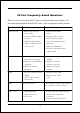
80 Port Frequently Asked Questions Below is a list of some basic POST Codes, possible problems and solutions. For more detailed information about POST Codes, refer to Appendix D in this manual. P O ST C O D E P r o bl e m So l uti o n FFh o r CFh 1 .B IO S c hip inse rte d 1 . Re inse rt the B IO S inc o rre c tly c hip 2 . Inc o rre c t BIO S update ve rsio n 3 . M ainbo ard pro ble m 4 . Add-o n c ard inse rte d inc o rre c tly. 2 .
Table of Contents Page Section 1 Introduction Package Contents ...................................................... 1- 1 Mainboard Features ................................................... 1- 2 System Block Diagram ............................................... 1- 6 Section 2 Specification Mainboard Specification ............................................ 2- 1 Section 3 Installation Mainboard Layout ..................................................... 3- 1 Easy Installation Procedure ........
PC Health Status ........................................................ 4- 17 Power BIOS Features ................................................. 4- 19 Defaults Menu ........................................................... 4- 22 Supervisor/User Password Setting ............................ 4- 23 Exit Selecting .............................................................. 4- 24 Section 5 RAID Configuration Introduction ...............................................................
Page Left Blank vi
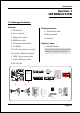
Introduction Section 1 INTRODUCTION 1-1 Package Contents Contents Powerpack items A. Mainboard L. ThermoStick cable B. User’s manual M.Mini heatsink C. Floppy drive cable N. Tool Pen D. HDD drive cable Optional Items E. CD (drivers and utilities) O. S/PDIF Module F. I/O Shield If you need the optional item, please contact your dealer for assistance. G. S-ATA data and power cable H. Game & COM bracket cable I. IEEE 1394 two ports cable J. Extra USB2.0 port cable K.
Introduction 1-2 Mainboard Features Brief Introduction Intel ® Pentium® 4 processors The Pentium 4 processor is designed to deliver performance across applications and usages where end-users can truly appreciate and experience the performance. The Pentium 4 processor delivers this world-class performance for consumer enthusiasts and business professional desktop PC users as well as for entry-level workstation users. Intel adds support for Hyper-Threading Technology to the Pentium 4 processor family.
Introduction Hardware Monitoring Hardware monitoring enables you to monitor various aspects of the system operation and status. This includes CPU temperature, voltage and fan speed in RPMs. Dual GbE LAN Two Gigabit-LAN controllers onboard running on the PCI-Express bus. This twin set of PCI-Express to Gigabit-LAN breaks traditional bandwidth barrier, delivering maximum 1000Mbps between internal and external network.
Introduction Special Features BIOS Features: & Magic Health Reports your system hardware status for every boot-up to help detect faults early. Monitor hardware status including CPU temperature, CPU/Memory/ Chipset voltage, fan RPM speed for chassis fan, CPU fan & Power supply fan. & EZ-Boot Simply press “ESC” to select your bootable device. No more hassle to search the BIOS menu, change and re-start. & PowerBIOS Supporting a full range of overclocking setting via BIOS.
Introduction & SP-ATA A S-ATA to IDE conversion device includes in this package. Older IDE harddrives can now be plugged to new Serial-ATA interface through this transition kit. SP-ATA even works for CD-ROM and DVD-ROM drives. & PISTON V Achieve ultimate overclocking with revolutionary 5-phase switching power. Using "true" five sets of independent switching block, PISTON V offers strong and stable CPU power while producing less heat compared to conventional PWM design.
Introduction 1-2 System Block Diagram Page 1-6
Specification Section 2 SPECIFICATION Mainboard Specification Processor ® ® Support Intel Pentium 4 5xx, 6xx and P4EE series processors up to 3.8+ GHz in LGA775 socket with 533/800/1066 MHz front-side system bus ® ® Support Intel Celeron D 3xx series processors up to 3.
Specification S-ATA RAID Four S-ATA ports with up to 150MBps bandwidth from ICH6R with RAID 0,1 support with Hot-Plug support LAN Two Gb Ethernet from onboard Marvell 88E8053 PCI-E*1 controller for Dual LAN with Virtual Cable Net-Diagnostic support 1394a Two 1394a ports with up to 400Mbps bandwidth from onboard VIA VT6307 1394 controller Audio Selectable 2, 6 or 8-CH audio from onboard ALC880 High Definition audio compliant CODEC with 20-bit ADC and 24-bit DAC resolution - Support CD-In, S/PDIF-in a
Specification BIOS Flash EEPROM with Award Plug&Play BIOS Support ACPI S3 (Suspend To RAM) mode in ACPI compliant O/S Support EZ Boot for fast bootable device selection Support Magic Health for system hardware status report during system boot-up Peripheral Interfaces ) At Rear Panel PS/2 keyboard and mouse ports One Parallel (printer) port One S/PDIF-Out Coaxial jack One S/PDIF-Out Optical One Serial port Two RJ45 LAN connector Four USB2.
Specification Front Panel Controller Supports Reset & Soft-Off switches Supports HDD & Power LEDs Supports PC speaker Supports Front Panel Audio connector Special Features Support KBPO function – Keyboard power on, turn on the computer from keyboard Support Wake-On-LAN by PME Support USB resume in S3 Onboard 80 Port LED display for system debugging PowerBIOS for excellent overclocking capabilities through - Programmable FSB, PCI-E and PCI Clock output frequency with 1MHz fine tuning - Supp
Installation Section 3 INSTALLATION Mainboard Layout Page 3-1
Installation Easy Installation Procedure The following must be completed before powering on your new system: 3-1. 3-2. 3-3. 3-4. CPU Installation Jumper Settings System Memory Expansion Slots 3-5. Device Connectors 3-1 CPU Installation Step 1 Carefully remove the plastic protection plate from the socket. Warning: The pins inside the CPU socket are fragile and are easily broken. Be careful not to touch them when installing the CPU.
Installation Step 4 Step 5 a) Put the CPU lid on the socket, and Place the CPU cooler on top of the socket. close the socket by lowering and Press its clips down firmly until it is locking the actuation lever. completely seated in the hole. b) Apply thermal compound to the top of the CPU and into the four holes around CPU area to install the cooler as shown. Step 6 a) Rotate the clips 90 degrees to lock the CPU cooler in place.
Installation 3-2 Jumper Settings JCMOS: Clear CMOS data Jumper If the CMOS data becomes corrupted or you forgot the supervisor or user password, clear the CMOS data to reconfigure the system back to the default values stored in the ROM BIOS. 1 Settings: 1-2: Normal (Default) 2-3: Clear CMOS To CMOS Clear data, please follow the steps below. 1. Turn off the system. 2. Change the jumper from “1-2” to “2-3” position for a few seconds. 3. Replace the jumper back to the “1-2” position. 4.
Installation 3-3 System Memory Configuration The mainboard accommodates four 240-pin DDR2 DIMM sockets. • Supports up to 4.0GB of 400/533MHz DDR2 SDRAM. • Supports dual channel memory interface. • Supports non-ECC memory and non-Registered DIMMs only. • Supports 256Mb/512Mb/1Gb DDR2 technologies in x8 and x16 devices only. • SPD (Serial Presence Detect) scheme for DIMM detection support. • Supports configurations defined in the JEDEC DDR2 DIMM specification only.
Installation Memory configurations supported: 1 DIMM (64-bit) DIMM#1 DIMM#2 2 DIMM (128-bit) SS/DS SS/DS SS/DS DIMM#3 DIMM#4 SS/DS SS/DS SS/DS SS/DS SS/DS 3 DIMM (128-bit) 4 DIM M (128-bit) SS/DS SS/DS SS/DS SS/DS SS/DS SS/DS SS/DS SS/DS SS/DS SS/DS SS/DS SS/DS SS/DS SS/DS * SS: Single-Sided DIMM, DS: Double-Sided DIMM Note: Using non-compliant memory with higher bus speeds (overclocking) may severely compromise the integrity of the system.
Installation 3-4 Expansion Slots PCI-E Slots The mainboard is equipped with two PCI-E*1 compliant with PCI Express 1.0a. PCI-E VGA Slots PCI-E VGA Slot PCI-E Slot PCI Slots The elongated PCI-E*16 is intended for PCI-E VGA card installation. PCI Slots The mainboard is equipped with three PCI slots. VGA Card Installation Caution 1. Remove the bracket (on the PC case) for the slot you intend to use. 2. Firmly press down the card into the slot until it is completely seated.
Installation 3-5 Device Connectors The I/O back panel for this mainboard is shown below. When installing the mainboard into the computer case, use the bundled I/O shield to protect this back panel. RJ45 LAN Parallel Port RJ45 LAN PS/2 Mouse PS/2 Keyboard 7.1 Audio Channel S/PDIF-out S/PDIF-out COM1 Coaxial Jack Optical USB2.
Installation FDD: Floppy Controller Connector IDE1: ATA-66/100 IDE Connector Supports up to 2 IDE devices from embedded IDE controller . IDE1 33 40 When using two IDE drives, one must be set to Master mode and the other to Slave mode. Refer to your disk drive user’s manual for information about selecting the proper drive switch settings.
Installation CFPA: Front Panel Audio Connector This audio connector connects to the audio jacks located on the front panel. Refer to your case manual to match the pin-out names. Front Line-out-R NC NC MIC_In Front Line-out-L 9 1 2 10 NC NC GND Key +5V CD-IN: CD Audio_IN Connector The CD-IN connector is used to receive audio form a CD-ROM drive, TV tuner or MPEG card.
Installation GAME1: Game/MIDI connector This port works well with any application that is compatible with the standard PC joystick. J1CY J1CX J1B1 J1B2 GND +5V +5V 1 15 2 16 J2CX +5V MIDI_In J2B2 J2B1 J2CY MIDI_Out COM2: Serial Port Connector The serial port can be used with modems, serial printers, remote display terminals, and other serial device. RTS RI DSR CTS NC 10 2 9 1 DCD TXD Ground RXD DTR C1394-1 / C1394-2 : IEEE 1394a (FireWire) Connectors This mainboard has 2 IEEE 1394a ports.
Installation SATA1 / SATA2 / SATA3 / SATA4: S-ATA Connectors These connectors enable you to connect Serial ATA devices that conform to the Serial ATA specification. 1 GND B+ BA- A+ GND GND SATA4 ~ Use the bundled SP-ATA Kit for older IDE hard SATA1 drives to interface to S-ATA. PW-ON button and RESET button: These buttons located onboard to turn on/off the system easily, especially while debugging or testing the system.
Installation LED1: 80 Port Debug LED Provides two-digit POST code to show why the system fail to boot. Allows quick and easy optimization. The LED will display the CPU temperature when you run the bundled USDM software. 80 Port Debug 7-segment LED display (Refer to Appendix D for POST codes) CUSB3/CUSB4: Four USB 2.0 ports This mainboard includes additional USB2.0 ports, identified by two 10-pin connector.
Installation CFP: Front Panel Connector HD_LED This LED will light up whenever the hard drive is being accessed. PWR_LED This connects to the power button of the system chassis CFP RST This switch allows you to reboot without having to power off the system thus prolonging the life of the power supply or system. PW_ON This is connected to the power button on the case. To use the Soft-Off by PWR-BTTN feature, refer to the Power Management Setup in the BIOS setup section of this manual.
Installation k Function 3-6 T her mo Stic Stick This mainboard is equipped with a digital thermometer capability to monitor any temperature. This is useful for measuring heat on peripherals such as VGA cards, hard disk drives, DIMMs or even on-board components such as chipset, MOSFETS, etc.
Installation 3-7 Power-On/Off (Remote) This board has a 24-pin ATX and a 4-pin ATX12V power supply connector to support power supplies with Remote On/Off feature. The 4-pin ATX12V connector must be plugged in for the system to operate safely. The chassis power button should be connected to the mainboard front panel PW_ON header.
Installation 3-9 ACPI S3 (Suspend To RAM) Function This mainboard supports the STR (Suspend To RAM) power management scheme by maintaining the appropriate power states in the RAM interface signals. The power source to the RAM is kept active during STR (ACPI S3). Advanced Configuration Power Interface (ACPI) provides many Energy Saving Features for operating systems that support Instant ON and QuickStartTM function. 1. To enable STR functionality to save system power : a.
Installation Page 3-18
BIOS Section 4 BIOS SETUP Main Menu The ROM BIOS contains a built-in Setup program which allows user to modify the basic system configuration and hardware parameters. The modified data is stored in a battery-backed CMOS, so that data will be retained even when the power is turned off. In general, the information saved in the CMOS RAM will stay unchanged unless there is a configuration change in the system, such as hard drive replacement or a device is added.
BIOS The main menu displays all the major selection items. Select the item you need to reconfigure. The selection is made by moving the cursor (press any direction (arrow key ) to the item and pressing the ‘Enter’ key. An on-line help message is displayed at the bottom of the screen as the cursor is moved to various items which provides a better understanding of each function. When a selection is made, the menu of the selected item will appear so that the user can modify associated configuration parameters.
BIOS 4-2 Advanced BIOS Features Selecting the “ADVANCED BIOS FEATURES” option in the CMOS SETUP UTILITY menu allows users to change system related parameters in the displayed menu. This menu shows all of the manufacturer’s default values for the board. Pressing the [F1] key displays a help message for the selected item. Figure 3: BIOS Features Setup CPU Feature This field is available only for Pentium® CPU with Prescott core.
BIOS CPU L3 Cache This controls the status of the processor’s internal Level Three cache. Options: Enables, Disabled. Hyper-Threading Technology Enables the CPU Hyper-Threading Technology. Options: Enables, Disabled. It is recommend to enable Hyper-Threading Technology on system with Windows XP and Linux 2.4 and disabling it for legacy OS. First /Second/Third/Other Boot Device The BIOS attempts to load the operating system from the devices in the sequence selected in these items.
BIOS APIC Mode This item allows you to enable APIC (Advanced Programmable Interrupt Controller) functionality. APIC is an Intel chip that provides symmetric multiprocessing (SMP) for its Pentium systems. Options: Enabled, Disabled. HDD S.M.A.R.T. Capability The S.M.A.R.T. (Self-Monitoring, Analysis, and Reporting Technology) system is a diagnostics technology that monitors and predicts device performance. S.M.A.R.T. Software resides on both the disk drive and the host computer.
BIOS DRAM Timing Selectable For setting DRAM Timing, select By SPD to follow Intel PC DDR SDRAM Serial Presence Detect Specification. Options: Manual, By SPD. CAS Latency Time This item specifies the number of clock cycles needed after a Column Address Strobe (CAS) signal before data can be read. Options: 2, 2.5, 3, Auto. DRAM RAS# to CAS# Delay This item sets the timing parameters for the system memory such as the CAS (Column Address Strobe) and RAS (Row Address Strobe). Options: 2, 3, 4, 5, Auto.
BIOS 4-4 Integrated Peripherals Figure 5: Integrated Peripherals Marvell Lan Boot ROM Enable/disable the onboard Marvell Lan Boot ROM. Options: Enabled, Disabled. PCI Express Function Scroll to PCI Express Function and press . The following screen appears: PCI Express Slot 1/2 PCI-E device disabled function. Options: Auto, Enabled, Disabled. Marvell Lan1/Lan2 Device Onboard PCI-E LAN device control function. Options: Auto, Enabled, Disabled.
BIOS On-Chip IDE Devices Scroll to On-Chip IDE Devices and press . The following screen appears: IDE HDD Block Mode IDE Block Mode allows the controller to access blocks of sectors rather than a single sector at a time. The default is Enabled. Options: Enabled, Disabled. IDE DMA transfer access Automatic data transfer between system memory and IDE device with minimum CPU intervention. This improves data throughput and frees CPU to perform other tasks. Options: Enabled, Disabled.
BIOS IDE Primary/Secondary Master/Slave UDMA Select the mode of operation for the IDE drive. Ultra DMA-33/66/100 implementation is possible only if your IDE hard drive supports it and the operating environment includes a DMA driver. If your hard drive and your system software both support Ultra DMA-33/66/100, select Auto to enable UDMA mode by BIOS. Options: Auto, Disabled. *** On-Chip Serial ATA Setting *** SATA Mode This item allows you to select Serial ATA Mode. Options: IDE, RAID, AHCI.
BIOS Onboard Devices Setup Scroll to Onboard Devices Setup and press . The following screen appears: USB Controller Enables the USB controller. Options: Disabled, Enabled. USB 2.0 Controller Enables the EHCI (USB2.0) controller. Options: Disabled, Enabled. USB Keyboard Support Enable/Disable support for USB keyboard under DOS. Options: Auto, Enabled, Disabled. USB Mouse Support Enable/Disable support for USB mouse under DOS. Options: Enabled, Disabled.
BIOS SuperIO Devices Scroll to SuperIO Devices and press . The following screen appears: Onboard FDC Controller Select “Enabled” if you wish to use onboard floppy disk controller (FDC). If you install an external FDC or the system has no floppy drive, select “Disabled “in this field. Options: Enabled, Disabled. Onboard Serial Port 1/2 Select an address and corresponding interrupt for the first and second serial ports. Options: 3F8/IRQ4, 2E8/IRQ3, 3E8/IRQ4, 2F8/IRQ3, Disabled, Auto.
BIOS 4-5 Power Management Setup Choose the “POWER MANAGEMENT SETUP” in the CMOS SETUP UTILITY to display the following screen. This menu allows the user to modify the power management parameters and IRQ signals. In general, these parameters should not be changed unless it’s absolutely necessary. Figure 6: Power Management ACPI Suspend Type This item allows you to select S1(Power-On-Suspend) or S3(Suspend-To-RAM) function. When set to “S3(STR)” or “S1&S3” the following two fields become available.
BIOS POWER ON Function Enables computer power on by keyboard, mouse, or hotkey activity. Password: Requires you to enter a password when using the keyboard to power on. Set the password in the next field “KB Power ON Password.” Hot KEY: (default) Enables you to use a hot key combination to power on the computer. Set the hot key combination in the “Hot Key Power ON” field. AnyKEY: Enables you to set any keyboard activity to power on the computer.
BIOS Max. saving: Maximum power savings. Inactivity period is 1 minute in each mode. Min. saving: Minimum power savings. Inactivity period is 1 hour in each mode. User define: Allows user to define PM Timers parameters to control power saving mode. Video Off Method This option allows you to select how the video will be disabled by the power management.
BIOS Power On by Ring When enabled, any modem activity awakens the system from soft-off state. Options: Enabled, Disabled. USB Wake-Up From S3 This item allows a USB device to wake-up the system from S3 suspend state. Options: Enabled, Disabled. Resume By Alarm When set to Enable alarm resume, you can set the date (of month) and time (hh:mm: ss), that will awaken a system which has been powered down. Options: Enabled, Disabled.
BIOS Init Display First This item is used to select whether to initialize the VGA or PCI first when the system boots. Options: PCI Slot, PCIEx. Resources Controlled By Determines what controls system PNP/PCI resources. The default is Auto (ESCD). Manual: PNP Card’s resources are controlled manually. The “IRQ Resources” field becomes available and you can set which IRQ-X and DMA-X are assigned to PCI and onboard devices. Auto: BIOS assigns the interrupt resource automatically.
BIOS 4-7 PC Health Status Figure 8: PC Health Status Show PC Health in POST When this function is enabled the PC Health information is displayed during the POST (Power On Self Test). Options: Enabled, Disabled. ACPI Shutdown Temperature This is the temperature that the computer will turn off the power to combat the effects of an overheating system. (requires ACPI to be enabled in Power Management BIOS and ACPI compliant operating system.) The default is Disabled.
BIOS 1.5V The voltage level of power supplied to VGA card. VDIMM(V) The voltage level of the DRAM. VBAT(V) The voltage level of the battery. + 12V, VCC, 5VSB(V) The voltage level of the switching power supply. CHASSIS Smart Fan Control This item lets you define a chassis temperature that the system will maintain by smartly adjusting the chassis fan. Options: Disabled, 35oC/95oF, 40oC/104oF, 45oC/113oF, 50oC/122oF, 55oC/131oF.
BIOS 4-8 Power BIOS Features This page lets you adjust various parameters to obtain improved performance for overclocking. Warning: Overclocking requires expert knowledge and risks permanent damage to system components. We recommend you leave these parameters at their default values for proper operation.
BIOS CPU CLOCK/SPEED Enables you to increment the CPU’s clock generator at 1MHz step. This works together with CPU Clock Ratio (below) to set the CPU operating frequency. CPU Clock Generator x CPU Clock Ratio = CPU Frequency For example, if you have a processor that is rated at 2.4GHz and the clock generator is 200MHz, then 200MHz x 12 = 2.4GHz Press to display the following screen: Key in the DEC (decimal) number for the CPU CLOCK/SPEED.
BIOS Key in the DEC (decimal) number for the PCI Express subtle tuning. System Memory Frequency Enables you to select a ratio of the DDR2 DRAM to match the installed DRAM frequency 400/533MHz. We recommend that you leave this item at the default value. Options available depend on system FSB.
BIOS In the following items, “Default Voltage” indicates the original factory value, and “New Voltage” indicates the value that you assign. CPU Vcore Voltage This item allows you to adjust the CPU Vcore voltage. Options: -0.0875V to +0.1875V in 0.0125V increments. We recommend that you leave this at the default value. Chipset Voltage This item allows you to adjust the Chipset voltage. Options: -0.00V to +0.15V in 0.05V increments. We recommend that you leave this at the default value.
BIOS 4-10 Supervisor/User Password Setting This function lets you set either Supervisor or User Password, or both, to prevent unauthorized changes to BIOS menus. supervisor password: full rights to enter and change options of the setup menus. user password: only enter but no rights to change options of the setup menus. When you select this function, the following message will appear at the center of the screen to assist you in creating a password.
BIOS 4-11 Exiting BIOS Save & Exit Setup Pressing on this item asks for confirmation: Save to CMOS and EXIT (Y/N)? Y Pressing “Y” stores the selections made in the menus in CMOS – a special section of memory that stays on after you turn your system off. The next time you boot your computer, the BIOS configures your system according to the Setup selections stored in CMOS. After saving the values the system is restarted again.
RAID Configuration Section 5 RAID CONFIGURATION Introduction This section gives a brief introduction on RAID-related background knowledge and a general procedure to setup RAID system on this mainboard. RAID Basics RAID (Redundant Array of Independent Disks) is a method of combining two or more hard disk drives into one logical unit known as a RAID array. The advantage of RAID is to provide better performance or data fault tolerance.
RAID Configuration RAID 0 (Striping) RAID 0 reads and writes sectors of data interleaved between multiple drives. If any disk member fails, it affects the entire array. The disk array data capacity is equal to the number of drive members times the capacity of the smallest member. The striping block size can be set from 4KB to 64KB. RAID 0 does not support fault tolerance. RAID 1 (Mirroring) RAID 1 writes duplicate data onto a pair of drives and reads both sets of data in parallel.
RAID Configuration Intel ICH6R RAID features • Support RAID 0, 1 • RAID 1 spare and auto-rebuild support • RAID 1 mirror restore without user interaction • Support for 2 RAID arrays on 4 ports • Support “RAID Ready” – pre-install RAID on one single drive and upgrade to RAID arrays in the future when more drives are added.
RAID Configuration Enable RAID Function For any RAID controller, the general procedure to setup a RAID system is shown below: Note: If you are not installing O/S into the RAID disks, you may skip Step 2 & Step3. Step 1: Create RAID Array RAID arrays are created using the RAID controller’s BIOS utility. For Intel ICH6R 1. Under CMOS setup, Integrated Peripherals section, set “SATA mode” to RAID, set “Intel RAID Boot ROM” to Enabled and restart the system. 2.
RAID Configuration Step 2: Prepare driver floppy When installing Windows XP/2000/NT4.0 into any RAID disk, the O/S setup will require a floppy disk containing the RAID driver. This step will show you how to prepare this driver floppy. There are 2 methods: Method 1 1. Insert the bundled CD into the CD-ROM drive 2. Boot the system from the CD-ROM 3. A menu of driver for various RAID controllers will appear 4. Insert a blank floppy into the A:drive 5.
RAID Configuration Step 4: Install Software utility for Windows After the O/S has been installed, you may install the RAID controller’s driver and software. The RAID software is a Windows-based utility with graphical user interface that provides an easy operating tool to configure and manage RAID arrays. 1)Insert the bundled CD into the CD-ROM drive. 2)When the main menu appears, click on the RAID driver corresponding to the controller you have configured in Step 1.
Drivers Installation Section 6 DRIVER INSTALLATION Easy Driver Installation Once the operating system has been installed, you need to install the drivers for the mainboard. Method 1 Method 2 Insert the bundled CD into the CD-ROM and the main menu screen will appear. The main menu displays links to the supported drivers, utilities and software. Method 1 This item installs all drivers automatically. Method 2 This item allows you to install the drivers selectively.
Drivers Installation Realtek Sound Manager Quick User-guide Introduction To obtain the best performance from your audio system, run the "Sound Manager" utility to adjust the settings to suit your needs. This section of the manual is intended to provide a quick user-guide to setup "Sound Manager". For more detailed information, refer to "Sound Manager manual" in the CD. 1. Right-click “Sound Effect” button on the task bar and select “Sound Manager”. Sound Effect : 2.
Drivers Installation Speaker Configuration: 3. This page displays the mainboards's phone jack function when a corresponding audio mode is selected. Figure 3 above shows the phone jack setup for 8 channel mode. 3D Audio Demo: 4. This page lets you test the 3D Positional Audio features.
Drivers Installation General: 5. This page displays information regarding the audio hardware and software. To remove "Sound Manager" icon from Windows Task bar, uncheck "Show icon in system tray". SPDIF: 6. This page shows S/PDIF-Out function on your system. S/PDIF-Out: Choose the type of audio source that will appear on the S/PDIFout connector.
Drivers Installation Audio Wizard: 7. This mainboard is equipped with jack re-tasking feature for Front Panel audio. Simply plug Microphone/ Line-out into any front panel jack and it will work. 8. Figure 8 below shows the back panel audio. The Jack sensing capability will warn you if a wrong jack is plugged and will guide you to the right jack.
Drivers Installation Page 6-6
Appendix Appendix A A-1 Update Your System BIOS Download the xxxxx.EXE file corresponding to your model from our website to an empty directory on your hard disk or floppy. Run the downloaded xxxxx.EXE file and it will self extract. Copy these extracted files to a bootable floppy disk. Note: The floppy disk should contain NO device drivers or other programs. 1. Type “A:\AWDFLASH and press Key. 2. You will see the following setup screen. 3. Please key in the xxxxx.bin BIOS file name. XXXX 4.
Appendix 5. Key in File Name to save previous BIOS to file. XXXX XXXXX xxxxx.bin xxxxx.bin 6. To confirm and proceed, please key in [Y] to start the programming. XXXX XXXXX xxxxx.bin xxxxx.bin 7. The BIOS update is finished. XXXX XXXXX xxxxx.
Appendix Appendix B B-1 Intel® Application Accelerator RAID Option ROM This Appendix describes the Intel Application Accelerator RAID Option ROM for creating a RAID array on SATA hard drives attached to ICH6R. This RAID BIOS provides a pre-OS user interface with basic functionality needed to create and delete RAID volumes in a pre-OS environment. This then allows the OS to be installed directly onto the RAID volume. 1.Creating a RAID Volume 1.
Appendix 3. Click Y to confirm. Note: Option #3 “Reset Hard Drives to Non-RAID” may also be used to delete a RAID volume. This mechanism is provided as a way to reset one or more SATA hard drives to non-RAID status, essentially deleting all metadata on the hard drives. This has the affect of deleting any RAID volumes present. This function is provided for re-setting the hard drives when there is a mismatch in RAID volume information on the hard drives, and Option #2 cannot be used. 3.
Appendix Appendix C C-1 Intel Matrix RAID Quick Guide This Appendix provides necessary steps to build a system with Intel Matrix RAID Technology combining both RAID 1 and RAID 0 volume on just two SATA hard drives. This special RAID array allows both fault tolerance and speed for optimum performance. Background Intel Matrix RAID Technology is the advanced ability for two RAID volumes to share the combined space of two hard drives being used in unison. Figure below shows Matrix RAID array.
Appendix 1. Insert the bundled CD the CD-ROM drive. 2. Boot the system from the CD-ROM drive. 3. A menu of various RAID controllers will appear. Look for the Intel ICH6R RAID driver. 4. Insert a blank floppy into the A:drive 5. Select the ICH6R driver to begin the copy into floppy drive. Setting Up a System with an Intel Matrix RAID Technology Configuration The following steps outline how to build a RAID 1 & RAID 0 system with Microsoft® Windows® XP installed using two SATA hard drives. 1.
Appendix disks, re-type the size to be half of what is shown by default. The second volume, when created, will automatically span the remainder of the two hard drives. 3.6. Press enter again to create the volume, press ‘Y’ to confirm. 3.7. Exit the Option ROM User Interface by selecting #4 in the main menu and ‘Y’ to confirm. ——————————Installing Windows———————————— 4. Begin Windows XP Setup by booting from the installation CD. 5.
Appendix C-4
Appendix Appendix D D-1 POST CODES POST (hex) DESCRIPTION CFh C0h Test CMOS R/W functionality. Early chipset initialization: - Disable shadow RAM - Disable L2 cache (socket 7 or below) - Program basic chipset registers Detect memory - Auto-detection of DRAM size, type and ECC. - Auto-detection of L2 cache (socket 7 or below) Expand compressed BIOS code to DRAM Call chipset hook to copy BIOS back to E000 & F000 shadow RAM.
Appendix 18h 19-1Ah 1Bh 1Ch 1Dh 1Eh 1Fh 20h 21h 22h 23h 24-26h 27h 28h 29h 2A-2Ch 2Dh 2E-32h 33h 34-3Bh 3Ch 3Dh 3Eh 3Fh 40h 41h 42h D-2 Detect CPU information including brand, SMI type (Cyrix or Intel) and CPU level (586 or 686). Reserved Initial interrupts vector table. If no special specified, all H/W interrupts are directed to SPURIOUS_INT_HDLR & S/W interrupts to SPURIOUS_soft_HDLR. Reserved Initial EARLY_PM_INIT switch.
Appendix 43h 44h 45-46h 47h 48h 49h 4A-4Dh 4Eh 4Fh 50h 51h 52h 53-54h 55h 56h 57h 58h 59h 5Ah 5Bh 5Ch 5Dh 5E-5Fh 60h 61-64h 65h 66h 67h 68h 69h 6Ah 6Bh 6Ch 6Dh Test 8259 functionality. Reserved Reserved Initialize EISA slot Reserved 1. Calculate total memory by testing the last double word of each 64K page. 2. Program writes allocation for AMD K5 CPU. Reserved 1. Program MTRR of M1 CPU 2. Initialize L2 cache for P6 class CPU & program CPU with proper cacheable range. 3.
Appendix 6Eh 6Fh 70-72h 73h 74h 75h 76h 77h 78h-79h 7Ah 7B-7Eh 7Fh 80h-81h 82h 83h 84h 85h 86-92h 93h 94h 95h 96h FFh D-4 Reserved 1. Initialize floppy controller 2. Set up floppy related fields in 40:hardware. Reserved (Optional Feature) Enter AWDFLASH.EXE if : -AWDFLASH is found in floppy drive. -ALT+F2 is pressed Reserved Detect & install all IDE devices: HDD, LS120, ZIP, CDROM….. Reserved Detect serial ports & parallel ports. Reserved Detect & install co-processor Reserved 1.