I815E Socket 370 Intel 815E Little Board USER’S MANUAL Version 1.
Acknowledgments Award is a registered trademark of Award Software International, Inc. PS/2 is a trademark of International Business Machines Corporation. Intel and Celeron are registered trademarks of Intel Corporation. Microsoft Windows is a registered trademark of Microsoft Corporation. Winbond is a registered trademark of Winbond Electronics Corporation. All other product names or trademarks are properties of their respective owners.
Table of Contents Introduction...............................................................1 Product Description ..........................................................1 Checklist...........................................................................2 Specifications....................................................................3 Board Dimensions.............................................................4 Installations ..............................................................
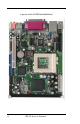
A picture of the I815E Embedded Board iv I815E User’s Manual
INTRODUCTION Introduction Product Description I815E is a high-performance flexible embedded board based on the Intel 815E chipset that contains the Graphics and Memory Controller Hub (GMCH), the I/O Controller Hub (ICH2) and the Firmware Hub (FWH). It supports 66/100/133MHz system bus, up to 1.4GHz CPU speed, integrated 2D/3D graphics accelerator, and PC100/PC133 SDRAM modules. With the ICH2, it is able to support UDMA33/66/100, four USB ports, and integrated LAN.
INTRODUCTION Checklist Your I815E package should include the items listed below.
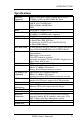
INTRODUCTION Specifications Processor Supported Chipset Socket 370 for Intel Celeron / Pentium III (FC-PGA), 533MHz~1.4GHz, 66/100/133MHz Bus Speed Intel 815E Chipset GMCH: 82815 544-PIN BGA ICH2: 82801BA 360-PIN BGA FWH BIOS Award BIOS; supports ACPI System Memory 1x DIMM socket supports up to 256MB capacity PC100/PC133 DIMM modules supported LPC I/O Chipset ITE IT8712 (keyboard controller is built-in) I/O Features 1x FDD (up to 2.
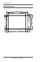
INTRODUCTION Board Dimensions 4 I815E User’s Manual
INSTALLATIONS Installations This section provides information on how to use the jumpers and connectors on the I815E in order to set up a workable system. The topics covered are: Installing the CPU.............................................................6 Installing the Memory (DIMM) .........................................7 Setting the Jumpers...........................................................8 Connectors on I815E.......................................................
INSTALLATIONS Installing the CPU The I815E board supports a Socket 370 processor socket for Intel Pentium III and Celeron processors. The Socket 370 processor socket comes with a lever to secure the processor. Raise this lever to about a 90° angle to allow the insertion of the processor. Place the processor into the socket by making sure the notch on the corner of the CPU corresponds with the notch on the inside of the socket.
INSTALLATIONS Installing the Memory (DIMM) The I815E board supports one 168-pin DIMM socket for a maximum total memory of 256MB in SDRAM type. The memory module capacities supported are 32MB, 64MB, 128MB and 256MB. Installing and Removing DIMMs To install the DIMM, locate the memory slot on the board and perform the following steps: 1. Hold the DIMM so that the two keys of the DIMM align with those on the memory slot. 2.
INSTALLATIONS Setting the Jumpers Jumpers are used on I815E to select various settings and features according to your needs and applications. Contact your supplier if you have doubts about the best configuration for your needs. The following lists the connectors on I815E and their respective functions. Jumper Locations on I815E............................................................... 9 Configuring the CPU Frequency ..................................................... 10 JP2: Clear CMOS Contents ....
INSTALLATIONS Jumper Locations on I815E Jumpers: JP2: Clear CMOS Contents JP5, JP7, JP8: RS232/422/485 (COM2) Selection JP6: BIOS Write Protect JP9, JP10: CPU Overclocking I815E User’s Manual 9
INSTALLATIONS Configuring the CPU Frequency The I815E board does not provide DIP switches to configure the processor speed (CPU frequency). However, the processor speed can be configured inside the BIOS Setup. Refer to the BIOS Setup section in this manual on how to change the processor speed. JP2: Clear CMOS Contents Use JP2, a 3-pin header, to clear the CMOS contents. Note that the ATX-power connector should be disconnected from the board before clearing CMOS.
INSTALLATIONS JP6: BIOS Write Protect JP6 can be used to protect the BIOS from being overwritten due to accidental modification or virus attacks. JP6 Write Protect Disabled Enabled JP9, JP10: CPU Overclocking Use JP9 and JP10 2-pin jumpers when overclocking the CPU bus speed from 66MHz to 100MHz or 100MHz to 133MHz. Refer to the table below.
INSTALLATIONS [ Connectors on I815E The connectors on I815E allows you to connect external devices such as keyboard, floppy disk drives, hard disk drives, printers, etc. The following table lists the connectors on I815E and their respective functions. Connector Locations on I815E........................................................ 13 IDE1, IDE2: Primary and Secondary IDE Connectors ................... 14 FDD1: Floppy Drive Connector......................................................
INSTALLATIONS Connector Locations on I815E Connectors: IDE1, IDE2: Primary and Secondary IDE Connectors FDD1: Floppy Drive Connector J2: System Function Connector FAN1: CPU Fan Power Connector FAN2, FAN3: System Fan Power Connectors J1, J3: Line-out and Microphone connectors J4, J5: CD In Connectors J6: Secondary RJ45 Connector (optional) J7: USB3/USB4 Connector J8: VGA CRT Connector J10: Parallel Port Connector J11: TV-Out Interface Connector J13: Wake On LAN Connector J15, J12: COM1 / COM2 Serial Ports
INSTALLATIONS IDE1, IDE2: Primary and Secondary IDE Connectors IDE1 IDE2 14 Signal Name Pin # Pin # Signal Name Reset IDE Host data 7 Host data 6 Host data 5 Host data 4 Host data 3 Host data 2 Host data 1 Host data 0 Ground DRQ0 Host IOW Host IOR IOCHRDY DACK0 IRQ14 Address 1 Address 0 Chip select 0 Activity 1 3 5 7 9 11 13 15 17 19 21 23 25 27 29 31 33 35 37 39 2 4 6 8 10 12 14 16 18 20 22 24 26 28 30 32 34 36 38 40 Ground Host data 8 Host data 9 Host data 10 Host data 11 Host data 12 Host dat
INSTALLATIONS FDD1: Floppy Drive Connector FDD1 is a 34-pin header and will support up to 2.88MB floppy drives.
INSTALLATIONS Speaker: Pins 1 - 4 This connector provides an interface to a speaker for audio tone generation. An 8-ohm speaker is recommended. Pin # 1 2 3 4 Signal Name Speaker out No connect Ground +5V Power LED: Pins 11 - 15 The power LED indicates the status of the main power switch.
INSTALLATIONS Turbo LED Connector: Pins 8 and 18 There is no turbo/deturbo function on the board. The Turbo LED on the control panel will always be On when attached to this connector. Pin # 8 18 Signal Name 5V Ground Reset Switch: Pins 9 and 19 The reset switch allows the user to reset the system without turning the main power switch off and then on again. Orientation is not required when making a connection to this header.
INSTALLATIONS FAN2, FAN3: System Fan Power Connectors FAN2 and FAN3 are 3-pin headers for the system fans. The fans must support 12V. 3 2 Pin # 1 2 3 1 Signal Name Ground +12V Rotation detection J1, J3: Line-out and Microphone connectors J1 ad J3 are connectors for Line out and Microphone jacks. J4, J5: CD In Connectors J4 and J5 are the CD-in connectors. Below is their pin out assignments.
INSTALLATIONS J7: USB3/USB4 Connector J7 is the onboard USB pin-header that supports an optional USB connector cable with two ports for USB3 and USB4. Pin # 1 8 2 7 3 6 4 5 Signal Name Vcc USBUSB+ Ground J8: VGA CRT Connector J8 is a DB-15 VGA connector located beside the COM1 port. The following table shows the pin-out assignments of this connector. Signal Name Pin # Red Blue GND GND N.C. N.C. HSYNC NC 1 3 5 7 9 11 13 15 I815E User’s Manual Pin # Signal Name 2 Green 4 N.C. 6 GND 8 GND 10 GND 12 N.C.
INSTALLATIONS J10: Parallel Port Connector J10 is a DB-25 external connector situated on top of the VGA and serial ports. The following table describes the pin-out assignments of this connector.
INSTALLATIONS J15, J12: COM1 / COM2 Serial Ports J15 (COM1) is a DB-9 connector, while J12 (COM2) is a 10-pin header. Refer to the table below for their pin assignments. COM1 Signal Name DCD, Data carrier detect RXD, Receive data TXD, Transmit data DTR, Data terminal ready Ground COM2 Pin # 1 2 3 4 5 Pin # 6 7 8 9 10 Signal Name DSR, Data set ready RTS, Request to send CTS, Clear to send RI, Ring indicator Not Used J12 (COM2) is jumper selectable for RS-232, RS-422 and RS-485.
INSTALLATIONS J16: USB and Primary RJ45 Connectors J16 consists of the primary RJ-45 connector (top) and two stacked USB ports. Refer to the section below for their respective pin assignments. USB1 USB2 Pin # 1 2 3 4 Signal Name Vcc USBUSB+ Ground J17: Smart Card Reader Interface J17 is a 14-pin header that provides interface for a Smart Card Reader. The table below shows the pin assignments of this pin header.
INSTALLATIONS J19: IrDA Connector J19 is used for an optional IrDA connector for wireless communication. Pin # Signal Name +5V IRRX IRTX 1 +5V 2 No connect 3 Ir RX N.C. GND 4 Ground 5 Ir TX J21: External Keyboard Connector Signal Name Vcc KBDAT_OUT KBDAT_IN Pin # 1 2 3 Pin # 4 5 6 Signal Name KBCLK_OUT KBCLK_IN GND J22: Game Port Connector J22 is a 16-pin game port pin header for devices such as joysticks.
INSTALLATIONS J24, J25: PS/2 Mouse and PS/2 Keyboard Connectors PS/2 Mouse PS/2 Keyboard Signal Name Keyboard data N.C. GND 5V Keyboard clock N.C. Keyboard 1 2 3 4 5 6 Mouse 1 2 3 4 5 6 Signal Name Mouse data N.C. GND 5V Mouse clock N.C. J26: ATX Power Supply Connector J26 is a 20-pin ATX power supply connector. Refer to the following table for the pin out assignments. 24 11 1 20 10 Signal Name 3.
BIOS SETUP BIOS Setup This chapter describes the different settings available in the Award BIOS that comes with the board. The topics covered in this chapter are as follows: BIOS Introduction ............................................................................ 26 BIOS Setup........................................................................................ 26 Standard CMOS Setup...................................................................... 28 Advanced BIOS Features......................
BIOS SETUP BIOS Introduction The Award BIOS (Basic Input/Output System) installed in your computer system’s ROM supports Intel Pentium II/III processors. The BIOS provides critical low-level support for a standard device such as disk drives, serial ports and parallel ports. It also adds virus and password protection as well as special support for detailed fine-tuning of the chipset controlling the entire system.
BIOS SETUP CMOS Setup Utility – Copyright © 1984-2001 Award Software Standard CMOS Features Advanced BIOS Features Advanced Chipset Features Integrated Peripherals Power Management Setup PnP/PCI Configurations PC Health Status Frequency/Voltage Control Load Fail-Safe Defaults Load Optimized Defaults Set Supervisor Password Set User Password Save & Exit Setup Exit Without Saving ESC : Quit F10 : Save & Exit Setup á â à ß : Select Item Time, Date, Hard Disk Type… The section below the setup items of the
BIOS SETUP Standard CMOS Setup “Standard CMOS Setup” choice allows you to record some basic hardware configurations in your computer system and set the system clock and error handling. If the board is already installed in a working system, you will not need to select this option. You will need to run the Standard CMOS option, however, if you change your system hardware configurations, the onboard battery fails, or the configuration stored in the CMOS memory was lost or damaged.
BIOS SETUP Time The time format is: Hour : 00 to 23 Minute : 00 to 59 Second : 00 to 59 To set the time, highlight the “Time” field and use the / or +/- keys to set the current time. IDE Primary HDDs / IDE Secondary HDDs The onboard PCI IDE connectors provide Primary and Secondary channels for connecting up to four IDE hard disks or other IDE devices. Each channel can support up to two hard disks; the first is the “Master” and the second is the “Slave”.
BIOS SETUP Video This field selects the type of video display card installed in your system. You can choose the following video display cards: EGA/VGA For EGA, VGA, SEGA, SVGA or PGA monitor adapters. (default) CGA 40 Power up in 40 column mode. CGA 80 Power up in 80 column mode. MONO For Hercules or MDA adapters. Halt On This field determines whether or not the system will halt if an error is detected during power up. No errors The system boot will not be halted for any error that may be detected.
BIOS SETUP Advanced BIOS Features This section allows you to configure and improve your system and allows you to set up some system features according to your preference.
BIOS SETUP CPU L2 Cache ECC Checking This field enables or disables the ECC (Error Correction Checking) checking of the CPU level-2 cache. The default setting is Enabled. Processor Number Feature When enabled, this feature allows external systems to detect the processor number/type of the CPU. Quick Power On Self Test When enabled, this field speeds up the Power On Self Test (POST) after the system is turned on. If it is set to Enabled, BIOS will skip some items.
BIOS SETUP Typematic Rate Setting When disabled, continually holding down a key on your keyboard will generate only one instance. When enabled, you can set the two typematic controls listed next. By default, this field is set to Disabled. Typematic Rate (Chars/Sec) When the typematic rate is enabled, the system registers repeated keystrokes speeds. Settings are from 6 to 30 characters per second.
BIOS SETUP Advanced Chipset Features This Setup menu controls the configuration of the chipset.
BIOS SETUP Video BIOS Cacheable The Setting Enabled allows caching of the video BIOS ROM at C0000h-F7FFFh, resulting in better video performance. However, if any program writes to this memory area, a system error may result. CPU Latency Timer The default setting for the CPU Latency Timer is Enabled. Delayed Transaction The chipset has an embedded 32-bit posted write buffer to support delay transactions cycles. Select Enabled to support compliance with PCI specification version 2.1.
BIOS SETUP Integrated Peripherals This section sets configurations for your hard disk and other integrated peripherals.
BIOS SETUP IDE Primary/Secondary Master/Slave UDMA These fields allow your system to improve disk I/O throughput to 33Mb/sec with the Ultra DMA/33 feature. The options are Auto and Disabled. USB Controller The options for this field are Enabled and Disabled. By default, this field is set to Enabled. USB Keyboard Support The options for this field are Enabled and Disabled. By default, this field is set to Disabled.
BIOS SETUP Onboard Serial/Parallel Port These fields allow you to select the onboard serial and parallel ports and their addresses. The default values for these ports are: Serial Port 1 3F8H/IRQ4 Serial Port 2 2F8H/IRQ3 Parallel Port 378H/IRQ7 UART Mode Select This field determines the UART 2 mode in your computer. The default value is Normal. Other options include IrDA and ASKIR. Parallel Port Mode This field allows you to determine parallel port mode function.
BIOS SETUP Power Management Setup The Power Management Setup allows you to save energy of your system effectively.
BIOS SETUP Video Off Method This field defines the Video Off features. There are three options. V/H SYNC + Blank Default setting, blank the screen and turn off vertical and horizontal scanning. DPMS Allows the BIOS to control the video display card if it supports the DPMS feature. Blank Screen This option only writes blanks to the video buffer. Video Off In Suspend When enabled, the video is off in suspend mode. The default setting is Yes.
BIOS SETUP Resume by Alarm This field enables or disables the resumption of the system operation. When enabled, the user is allowed to set the Date and Time. Reload Global Timer Events The HDD, FDD, COM, LPT Ports, and PCI PIRQ are I/O events which can prevent the system from entering a power saving mode or can awaken the system from such a mode. When an I/O device wants to gain the attention of the operating system, it signals this by causing an IRQ to occur.
BIOS SETUP PNP/PCI Configurations This option configures the PCI bus system. All PCI bus systems on the system use INT#, thus all installed PCI cards must be set to this value. CMOS Setup Utility – Copyright © 1984-2001 Award Software PnP/PCI Configurations Reset Configuration Data Disabled ITEM HELP Menu Level Resources Controlled By Auto (ESCD) IRQ Resources Press Enter PCI/VGA Palette Snoop Disabled Default is Disabled.
BIOS SETUP PC Health Status This section shows the parameters in determining the PC Health Status. These parameters include temperatures, fan speeds and voltages. CMOS Setup Utility – Copyright © 1984-2001 Award Software PC Health Status Shutdown Temperature Vcore (V) Disabled 1.63V +1.8(V) 1.79V VCC3(V) 3.37V +5(V) 5.05V +12(V) 12.09V -12(V) -5(V) (-)12.03V -5.05V 5VSB(V) 4.70V Voltage Battery 3.24V System Temp. 41°C CPU Temp. System Temp.
BIOS SETUP Frequency/Voltage Control This section shows the user how to configure the processor frequency. CMOS Setup Utility – Copyright © 1984-2001 Award Software Frequency/Voltage Control Auto Detect DIMM/PCI Clk Disabled Spread Spectrum Disabled Host CPU/PCI Clock Default CPU Clock Ratio X3 ITEM HELP Menu Level Auto Detect DIMM/PCI Clk This field enables or disables the auto detection of the DIMM/PCI clock. The default setting is Disabled.
BIOS SETUP Load Fail-Safe Defaults This option allows you to load the troubleshooting default values permanently stored in the BIOS ROM. These default settings are non-optimal and disable all high-performance features. Load Setup Defaults This option allows you to load the default values to your system configuration. These default settings are optimal and enable all high performance features. Set Supervisor/User Password These two options set the system password.
BIOS SETUP This page is intentionally left blank.
DRIVERS INSTALLATION Drivers Installation This section describes the installation procedures for software and drivers under the Windows 98, Windows NT 4.0 and Windows 2000. The software and drivers are included with the board. If you find the items missing, please contact the vendor where you made the purchase. The contents of this section include the following: I815E Windows 98 Drivers Installation ...........................48 Intel Software Installation Utility.........................................
DRIVERS INSTALLATION I815E Windows 98 Drivers Installation Intel Software Installation Utility The Intel Chipset Software Installation Utility will enable Plug & Play INF support for Intel chipset components. Follow the instructions below to complete the installation under Windows 98. 1. Insert the CD that comes with the board. In the initial screen, Intel 815(E) Driver. 2. In the Intel 815 Driver screen, click Intel Chipset Software Installation Utility. 3.
DRIVERS INSTALLATION Intel Ultra ATA Storage Driver Follow the steps below to install Intel Ultra ATA Storage Driver with the InstallShield Wizard under Windows 98. 1. Insert the CD that comes with the board. In the initial scrren, click Intel 815(E) Driver. 2. In the Intel 815 Driver screen, click Intel Ultra ATA IDE Driver. 3. The Welcome screen of the Install Shield Wizard for Intel Ultra ATA Storage Driver appears. To continue, click Next. 4.
DRIVERS INSTALLATION 6. You are now asked to select a program folder. Click Next to accept the default program folder or enter the folder name you prefer. 7. The InstallShield Wizard has completed installation. Click Finish for the computer to restart and changes to take effect.
DRIVERS INSTALLATION Intel 815E Chipset VGA Driver Follow the steps below to install Intel 81x Family Chipset Graphics Driver Software under Windows 98. 1. Insert the CD that comes with the board. In the initial scrren, click Intel 815(E) Driver. 2. In the Intel 815 Driver screen, click Intel 815x Chipset Graphics Driver. 3. The Welcome screen of the Intel 81x Family Chipset Graphics Driver Software Setup program appears. To continue, click Next. 4.
DRIVERS INSTALLATION SigmaTel AC97 Audio Drivers Follow the steps below to install SigmaTel AC97 Audio Drivers on your system under Windows 98. 1. Insert the CD that comes with the board. In the initial scrren, click Intel 815(E) Driver. 2. In the Intel 815 Driver screen, click SigmaTel AC97 Audio Driver. 3. The Welcome screen of the SigmaTel AC97 Audio Driver Setup program appears. To continue, click Next. 4. Click Yes to accept the software license agreement and proceed with the installation process. 5.
DRIVERS INSTALLATION 6. The Setup program has now completed installation. Click Finish for the computer to restart and changes to take effect. 7. After the system has restarted, a screen would appear saying it was able to find the device “Intel AC’97 Audio Controller.” Click Next to continue. 8. Now click Select to “Search for the best river for your device (Recommended).” Click Next, then click Select to “specify a location”.
DRIVERS INSTALLATION I815E Windows NT 4.0 Drivers Installation Intel Ultra ATA Storage Driver Follow the steps below to install Intel Ultra ATA Storage Driver with the InstallShield Wizard under Windows NT 4.0. 1. Insert the CD that comes with the board. In the initial scrren, click Intel 815(E) Driver. 2. In the Intel 815 Driver screen, click Intel Ultra ATA IDE Driver. 3. The Welcome screen of the Install Shield Wizard for Intel Ultra ATA Storage Driver appears. To continue, click Next.
DRIVERS INSTALLATION 4. Click Yes to accept the software license agreement and proceed with the installation process. 5. You are now required to Select the folder where Setup will install files. Click Next to accept the default folder or click Browse to configure the location.
DRIVERS INSTALLATION 6. You are now asked to select a program folder. Click Next to accept the default program folder or enter the folder name you prefer. 7. The InstallShield Wizard has completed installation. Click Finish for the computer to restart and changes to take effect.
DRIVERS INSTALLATION Intel 815E Chipset VGA Driver Follow the steps below to install Intel 81x Family Chipset Graphics Driver Software under Windows NT 4.0. 1. Insert the CD that comes with the board. In the initial scrren, click Intel 815(E) Driver. 2. In the Intel 815 Driver screen, click Intel 81x Chipset Graphics Driver. 3. The Welcome screen of the Intel 81x Family Chipset Graphics Driver Software Setup program appears. To continue, click Next.
DRIVERS INSTALLATION 4. Click Yes to accept the software license agreement and proceed with the installation process. 5. The Setup program has now completed installation. Click Finish for the computer to restart and changes to take effect.
DRIVERS INSTALLATION SigmaTel AC97 Audio Drivers Follow the steps below to install SigmaTel AC97 Audio Drivers on your system under Windows NT 4.0. 1. Insert the CD that comes with the board. In the initial scrren, click Intel 815(E) Driver. 2. In the Intel 815 Driver screen, click SigmaTel AC97 Audio Driver. 3. The Welcome screen of the SigmaTel AC97 Audio Driver Setup program appears. To continue, click Next.
DRIVERS INSTALLATION 4. Click Yes to accept the software license agreement and proceed with the installation process. 5. Select Install and click Next to install SigmaTel AC97 Audio Drivers on your system.
DRIVERS INSTALLATION 6. The Setup program has now completed installation. Click Finish for the computer to restart and changes to take effect. 7. After the system has restarted, a screen would appear showing some installation information. Restart the system when prompted to complete the audio driver installation.
DRIVERS INSTALLATION I815E Windows 2000 Drivers Installation Intel Software Installation Utility The Intel Chipset Software Installation Utility will enable Plug & Play INF support for Intel chipset components. Follow the instructions below to complete the installation under Windows 2000. 1. Insert the CD that comes with the board. In the initial scrren, click Intel 815(E) Driver. 2. In the Intel 815 Driver screen, click Intel Chipset Software Installation Utility. 3.
DRIVERS INSTALLATION Intel Ultra ATA Storage Driver Follow the steps below to install Intel Ultra ATA Storage Driver with the InstallShield Wizard under Windows 98. 1. Insert the CD that comes with the board. In the initial scrren, click Intel 815(E) Driver. 2. In the Intel 815 Driver screen, click Intel Ultra ATA IDE Driver. 3. The Welcome screen of the Install Shield Wizard for Intel Ultra ATA Storage Driver appears. To continue, click Next. 4.
DRIVERS INSTALLATION 6. You are now asked to select a program folder. Click Next to accept the default program folder or enter the folder name you prefer. 7. The InstallShield Wizard has completed installation. Click Finish for the computer to restart and changes to take effect.
DRIVERS INSTALLATION Intel 815E Chipset VGA Driver Follow the steps below to install Intel 81x Family Chipset Graphics Driver Software under Windows 2000. 1. Insert the CD that comes with the board. In the initial scrren, click Intel 815(E) Driver. 2. In the Intel 815 Driver screen, click Intel 815x Chipset Graphics Driver. 3. The Welcome screen of the Intel 815x Family Chipset Graphics Driver Software Setup program appears. To continue, click Next. 4.
DRIVERS INSTALLATION SigmaTel AC97 Audio Drivers Follow the steps below to install SigmaTel AC97 Audio Drivers on your system under Windows 2000. 1. Insert the CD that comes with the board. The CD will autorun and show an initial screen. Click Intel 815(E) Driver. 2. Click SigmaTel AC97 Audio Driver. 3. The Welcome screen of the SigmaTel AC97 Audio Driver Setup program appears. To continue, click Next. 4. Click Yes to accept the software license agreement and proceed with the installation process. 5.
DRIVERS INSTALLATION 6. A window appears indicating that the software to be installed does not contain a Microsoft digital signature. Click Yes to continue the installation process. 7. The Setup program has now completed installation. Click Finish for the computer to restart and changes to take effect.
DRIVERS INSTALLATION Intel 82559 LAN Drivers Installation Introduction Intel 82559 a 32-bit 10/100MBps Ethernet controller for PCI local bus-compliant PCs. It supports bus mastering architecture, and auto-negotiation feature that can be used for both 10Mbps and 100Mbps connection. Making Floppy Disks for NetWare and Windows Installation You need to use a floppy disk to install the LAN drivers. Use the MAKEDISK.BAT utility located in the \LAN\I8255X\MAKEDISK directory on the CD.
DRIVERS INSTALLATION Installing LAN Drivers for Windows 95 Follow these steps to install the Intel 82559 LAN/Ethernet driver for Windows 95: 1. From the Control Panel, double-click the System icon. 2. Click the Device Manager tab. 3. Double-click Other Devices (question mark icon) in the list area. 4. Double-click a PCI Ethernet Controller. 5. Click the Driver tab, then click Update Driver. 6.
DRIVERS INSTALLATION Installing LAN Drivers for Windows NT Follow the steps below to install the PCI Ethernet/LAN drivers Windows NT 4.0. 1. Under the Windows NT 4.0 environment, click Start à Control Panel. Double click Network à Adapters à Add. 2. Select “Have disk … ” and insert the floppy diskette containing the Ethernet drivers for Windows NT 4.0 into the FDD drive, then click OK. 3. Click OK à Close, and then enter IP address. 4. Restart the system for changes to take effect.
DRIVERS INSTALLATION TV Out Drivers Installation Introduction The I815E 5.25” embedded board supports the optional TV out function with the optional IB742 TV Out Daughter Card. After you have installed the IBD742 daughter card onto I815E, install the TV-Out drivers by doing the following procedure. 1. Insert the diskette containing the TV Out driver files into the floppy disk drive. Under Windows 98, click START, then click RUN.
DRIVERS INSTALLATION 2. Click Next to continue with the Setup program. 3. Click Next to begin copying the program files.
DRIVERS INSTALLATION 4. After file copying is finished, click Finish to restart the computer and for changes to take effect.
DRIVERS INSTALLATION This page was intentionally left blank.
APPENDIX Appendix A. I/O Port Address Map B. Interrupt Request Lines (IRQ) A. I/O Port Address Map Each peripheral device in the system is assigned a set of I/O port addresses which also becomes the identity of the device. The following table lists the I/O port addresses used.
APPENDIX B. Interrupt Request Lines (IRQ) Peripheral devices use interrupt request lines to notify CPU for the service required. The following table shows the IRQ used by the devices on board.