
Datasheet


Electrical Specifications
24 Datasheet
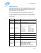
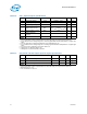
Table 10. GTL+ Signal Group DC Specifications
Symbol Parameter Min Max Unit Notes
1
NOTES:
1. Unless otherwise noted, all specifications in this table apply to all processor frequencies.
V
IL
Input Low Voltage -0.10 GTLREF – 0.10 V
2, 3
2. V
IL
is defined as the voltage range at a receiving agent that will be interpreted as a logical low
value.
3. The V
TT
referred to in these specifications is the instantaneous V
TT
.
V
IH
Input High Voltage GTLREF + 0.10 V
TT
+ 0.10 V
3, 4, 5
4. V
IH
is defined as the voltage range at a receiving agent that will be interpreted as a logical high
value.
5. V
IH
and V
OH
may experience excursions above V
TT
.
V
OH
Output High Voltage V
TT
– 0.10 V
TT
V
3, 5
I
OL
Output Low Current N/A
V
TT_MAX
/
[(R
TT_MIN
)+(2*R
ON_MIN
)]
A-
I
LI
Input Leakage Current N/A ± 200 µA
6
6. Leakage to V
SS
with land held at V
TT
.
I
LO
Output Leakage
Current
N/A ± 200 µA
7
7. Leakage to V
TT
with land held at 300 mV.
R
ON
Buffer On Resistance 10 13 Ω
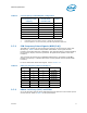
Table 11. Open Drain and TAP Output Signal Group DC Specifications
Symbol Parameter Min Max Unit Notes
1
NOTES:
1. Unless otherwise noted, all specifications in this table apply to all processor frequencies.
V
OL
Output Low Voltage 0 0.20 V -
I
OL
Output Low Current 16 50 mA
2
2. Measured at V
TT
* 0.2.
I
LO
Output Leakage Current N/A ± 200 µA
3
3. For Vin between 0 and V
OH
.