
Datasheet


Functional Description
Intel® Xeon® Processor D-1500 Product Family 121
Datasheet - Volume 1 of 4: Integrated Platform Controller Hub
March 2015
3.15.3 Theory of Operation
3.15.3.1 Standard ATA Emulation
Intel® Xeon® Processor D-1500 Product Family contains a set of registers that shadow
the contents of the legacy IDE registers. The behavior of the Command and Control
Block registers, PIO, and DMA data transfers, resets, and interrupts are all emulated.
Note: Intel® Xeon® Processor D-1500 Product Family will assert INTR when the master
device completes the EDD command regardless of the command completion status of
the slave device. If the master completes EDD first, an INTR is generated and BSY will
remain '1' until the slave completes the command. If the slave completes EDD first,
BSY will be '0' when the master completes the EDD command and asserts INTR.
Software must wait for busy to clear (0) before completing an EDD command, as
required by the ATA5 through ATA7 (T13) industry standards.
3.15.3.2 48-Bit LBA Operation
The SATA host controller supports 48-bit LBA through the host-to-device register FIS
when accesses are performed using writes to the task file. The SATA host controller will
ensure that the correct data is put into the correct byte of the host-to-device FIS.
There are special considerations when reading from the task file to support 48-bit LBA
operation. Software may need to read all 16-bits. Since the registers are only 8-bits
wide and act as a FIFO, a bit must be set in the device/control register, which is at
offset 3F6h for primary and 376h for secondary (or their native counterparts).
If software clears Bit 7 of the control register before performing a read, the last item
written will be returned from the FIFO. If software sets Bit 7 of the control register
before performing a read, the first item written will be returned from the FIFO.
3.15.4 SATA Swap Bay Support
Intel® Xeon® Processor D-1500 Product Family provides for basic SATA swap bay
support using the PSC register configuration bits and power management flows. A
device can be powered down by software and the port can then be disabled, allowing
removal and insertion of a new device.
Note: This SATA swap bay operation requires board hardware (implementation specific),
BIOS, and operating system support.
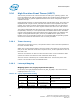
Host & Link Initiated Power
Management
Capability for the host controller or device to request Partial and Slumber
interface power states
Staggered Spin-Up Enables the host the ability to spin up hard drives sequentially to prevent
power load problems on boot
Command Completion Coalescing Reduces interrupt and completion overhead by allowing a specified
number of commands to complete and then generating an interrupt to
process the commands
Feature Description