GD82559ER Fast Ethernet** PCI Controller Networking Silicon Datasheet Product Features ■ Optimum Integration for Lowest Cost Solution — Integrated IEEE 802.
GD82559ER - Networking Silicon Revision History Revision Date Revision Description Mar. 1999 1.0 First release. Information in this document is provided in connection with Intel products. No license, express or implied, by estoppel or otherwise, to any intellectual property rights is granted by this document.
Networking Silicon — GD82559ER Contents 1. INTRODUCTION ............................................................................................................................. 1 1.1 1.2 2. GD82559ER ARCHITECTURAL OVERVIEW ................................................................................ 3 2.1 2.2 2.3 2.4 3. 3.3 3.4 3.5 4.2 4.3 4.4 4.5 4.6 82559ER Initialization .......................................................................................................13 4.1.
GD82559ER — Networking Silicon 6.2 6.3 6.4 7. PCI CONFIGURATION REGISTERS ........................................................................................... 47 7.1 8. LAN (Ethernet) PCI Configuration Space ......................................................................... 47 7.1.1 PCI Vendor ID and Device ID Registers .......................................................... 47 7.1.2 PCI Command Register .................................................................................
Networking Silicon — GD82559ER 8.2 9. PHY UNIT REGISTERS ................................................................................................................65 9.1 9.2 9.3 10. MDI Registers 0 - 7...........................................................................................................65 9.1.1 Register 0: Control Register Bit Definitions .....................................................65 9.1.2 Register 1: Status Register Bit Definitions .................................
GD82559ER — Networking Silicon vi Datasheet
Networking Silicon — GD82559ER 1. Introduction 1.1 GD82559ER Overview The 82559ER is part of Intel's second generation family of fully integrated 10BASE-T/100BASETX LAN solutions. The 82559ER consists of both the Media Access Controller (MAC) and the physical layer (PHY) combined into a single component solution. 82559 family members build on the basic functionality of the 82558 and contain power management enhancements.
GD82559ER — Networking Silicon 2 Datasheet
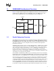
Networking Silicon — GD82559ER 2. GD82559ER Architectural Overview Figure 1 is a high level block diagram of the 82559ER. It is divided into four main subsystems: a parallel subsystem, a FIFO subsystem, the 10/100 Mbps Carrier-Sense Multiple Access with Collision Detect (CSMA/CD) unit, and the 10/100 Mbps physical layer (PHY) unit.
GD82559ER — Networking Silicon operate independently. Control is switched between the two units according to the microcode instruction flow. The independence of the Receive and Command units in the micromachine allows the 82559ER to interleave commands and receive incoming frames, with no real-time CPU intervention. The 82559ER contains an interface to an external Flash memory, and external serial EEPROM. These two interfaces are multiplexed.
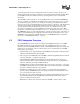
Networking Silicon — GD82559ER 2.3 10/100 Mbps Serial CSMA/CD Unit Overview The CSMA/CD unit of the 82559ER allows it to be connected to either a 10 or 100 Mbps Ethernet network. The CSMA/CD unit performs all of the functions of the 802.3 protocol such as frame formatting, frame stripping, collision handling, deferral to link traffic, etc. The CSMA/CD unit can also be placed in a full-duplex mode, which allows simultaneous transmission and reception of frames. 2.
GD82559ER — Networking Silicon 6 Datasheet
Networking Silicon —GD82559ER 3. Signal Descriptions 3.1 Signal Type Definitions Type Name Description IN Input The input pin is a standard input only signal. OUT Output The output pin is a Totem Pole Output pin and is a standard active driver. T/S Tri-State The tri-state pin is a bidirectional, input/output pin. S/T/S Sustained Tri-State The sustained tri-state pin is an active low tri-state signal owned and driven by one agent at a time.
GD82559ER — Networking Silicon 3.2.2 Interface Control Signals Symbol Name and Function S/T/S Cycle Frame. The cycle frame signal is driven by the current master to indicate the beginning and duration of a transaction. FRAME# is asserted to indicate the start of a transaction and de-asserted during the final data phase. S/T/S Initiator Ready.
Networking Silicon —GD82559ER 3.2.3 System and Power Management Signals Symbol CLK CLKRUN# IN/OUT O/D Clock. The Clock signal provides the timing for all PCI transactions and is an input signal to every PCI device. The 82559ER requires a PCI Clock signal (frequency greater than or equal to 16 MHz) for nominal operation. The 82559ER supports Clock signal suspension using the Clockrun protocol. Clockrun. The Clockrun signal is used by the system to pause or slow down the PCI Clock signal.
GD82559ER — Networking Silicon Symbol 3.4 Name and Function FLA[13]/ EEDI OUT Flash Address[13]/EEPROM Data Input. During Flash accesses, this multiplexed pin acts as the Flash Address [13] output signal. During EEPROM accesses, it acts as serial output data to the EEPROM Data Input signal. FLA[12:8] OUT Flash Address[12:8]. These pins are used as Flash address outputs to support 128 Kbyte Flash addressing. FLA[7]/ CLKENB T/S Flash Address[7]/Clock Enable.
Networking Silicon —GD82559ER 3.5 PHY Signals Symbol Type Name and Function X1 A/I Crystal Input One. X1 and X2 can be driven by an external 3.3 V 25 MHz crystal. Otherwise, X1 may be driven by an external metal-oxide semiconductor (MOS) level 25 MHz oscillator when X2 is left floating. X2 A/O Crystal Input Two. X1 and X2 can be driven by an external 3.3 V 25 MHz crystal. Otherwise, X1 may be driven by an external MOS level 25 MHz oscillator when X2 is left floating.
GD82559ER — Networking Silicon 12 Datasheet
Networking Silicon — GD82559ER 4. GD82559ER Media Access Control Functional Description 4.1 82559ER Initialization The 82559ER has four sources for initialization. They are listed according to their precedence: 1. ALTRST# Signal 2. PCI RST# Signal 3. Software Reset (Software Command) 4. Selective Reset (Software Command) 4.1.1 Initialization Effects on 82559ER Units The following table shows the effect of each of the different initialization sources on major portions of the 82559ER.
GD82559ER — Networking Silicon 4.2 PCI Interface 4.2.1 82559ER Bus Operations After configuration, the 82559ER is ready for normal operation. As a Fast Ethernet controller, the role of the 82559ER is to access transmitted data or deposit received data. In both cases the 82559ER, as a bus master device, will initiate memory cycles via the PCI bus to fetch or deposit the required data.
Networking Silicon — GD82559ER The figures below show CSR zero wait-state I/O read and write cycles. In the case of accessing the Control/Status Registers, the CPU is the initiator and the 82559ER is the target of the transaction. CLK SYSTEM 1 2 3 4 5 6 7 8 9 FRAME# AD ADDR C/BE# I/O RD DATA BE# 82559ER IRDY# TRDY# DEVSEL# STOP# Figure 2.
GD82559ER — Networking Silicon controls the TRDY# signal and asserts it from the data access. The 82559ER allows the CPU to issue only one I/O write cycle to the Control/Status Registers, generating a disconnect by asserting the STOP# signal. This is true for both memory mapped and I/O mapped accesses. 4.2.1.1.2 Flash Buffer Accesses The CPU accesses to the Flash buffer are very slow. For this reason the 82559ER issues a targetdisconnect at the first data access.
Networking Silicon — GD82559ER SYSTEM CLK FRAME# AD C/BE# DATA ADDR MEM WR BE# 82559ER IRDY# TRDY# DEVSEL# STOP# Figure 5. Flash Buffer Write Cycle Write Accesses: The CPU, as the initiator, drives the address lines AD[31:0], the command and byte enable lines C/BE#[3:0] and the control lines IRDY# and FRAME#. It also provides the 82559ER with valid data immediately after asserting IRDY#.
GD82559ER — Networking Silicon SYSTEM CLK FRAME# 82559ER IRDY# TRDY# DEVSEL# STOP# Figure 6. PCI Retry Cycle Note: The 82559ER is considered the target in the above diagram; thus, TRDY# is not asserted. 4.2.1.1.4 Error Handling Data Parity Errors: The 82559ER checks for data parity errors while it is the target of the transaction. If an error was detected, the 82559ER always sets the Detected Parity Error bit in the PCI Configuration Status register, bit 15.
Networking Silicon — GD82559ER 8 depict memory read and write burst cycles. For bus master cycles, the 82559ER is the initiator and the host main memory (or the PCI host bridge, depending on the configuration of the system) is the target. CLK 82559ER 1 2 3 4 5 6 7 8 DATA DATA 9 10 9 10 FRAME# ADDR AD C/BE# DATA MR DATA DATA BE# BE# SYSTEM IRDY# TRDY# DEVSEL# Figure 7.
GD82559ER — Networking Silicon Byte Count value indicates the maximum number of transmit DMA PCI cycles that will be completed after an 82559ER internal arbitration. (Details on the Configure command are described in the Software Developer’s Manual.) The 82559ER, as the initiator, drives the address lines AD[31:0], the command and byte enable lines C/BE#[3:0] and the control lines IRDY# and FRAME#. The 82559ER asserts IRDY# to support zero wait state burst cycles.
Networking Silicon — GD82559ER 1. Minimum transfer of one cache line 2. Active byte enable bits (or BE#[3:0] are all low) during MWI access 3. The 82559ER may cross the cache line boundary only if it intends to transfer the next cache line too. To ensure the above conditions, the 82559ER may use the MWI command only if the following conditions hold: 1. The Cache Line Size (CLS) written in the CLS register during PCI configuration is 8 or 16 Dwords. 2. The accessed address is cache line aligned. 3.
GD82559ER — Networking Silicon • This feature is not recommended for use in non-cache line oriented systems since it may cause shorter bursts and lower performance. • This feature should be used only when the CLS register in PCI Configuration space is set to 8 or 16 Dwords. • The 82559ER reads all control data structures (including Receive Buffer Descriptors) from the first Dword (even if it is not required) to maintain cache line alignment. 4.2.1.2.
Networking Silicon — GD82559ER 4.2.4 Power States The 82559ER’s power management register implements all four power states as defined in the Power Management Network Device Class Reference Specification, Revision 1.0. The four states, D0 through D3, vary from maximum power consumption at D0 to the minimum power consumption at D3. PCI transactions are only allowed in the D0 state, except for host accesses to the 82559ER’s PCI configuration registers.
GD82559ER — Networking Silicon 4.2.4.4 D3 Power State In the D3 power state, the 82559ER has the same capabilities and consumes the same amount of power as it does in the D2 state. However, it enables the PCI system to be in the B3 state. If the PCI system is in the B3 state (in other words, no PCI power is present), the 82559ER provides wake-up capabilities if it is connected to an auxiliary power source in the system.
Networking Silicon — GD82559ER .
GD82559ER — Networking Silicon In a LAN on Motherboard solution, the PCI power good signal is supplied by the system. In network adapter implementations, the PCI power good signal can be either generated locally using an external analog device, or connected directly to the PCI reset signal. In designs, that use both the ISOLATE# and RST# pins of the 82559ER, the PCI power good signal should envelope ISOLATE#, as shown below.
Networking Silicon — GD82559ER • ISOLATE# trailing edge The internal initialization signal resets the PCI Configuration Space, MAC configuration, and memory structure. The behavior of the PCI RST# signal and the internal 82559ER initialization signal are shown in the figure below. D0 - D2 power state PCI RST# Internal hardware reset D3 power state PCI RST# Internal hardware reset 640 ns Internal reset due to ISOLATE# ISOLATE# Internal hardware reset 640 ns Figure 10.
GD82559ER — Networking Silicon 4.2.5.2 Link Status Change Event The 82559ER link status indication circuit is capable of issuing a PME on a link status change from a valid link to an invalid link condition or vice versa. The 82559ER reports a PME link status event in all power states. The PME# signal is gated by the PME Enable bit in the PMCSR and the CSMA Configure command, which is described in the Software Developer’s Manual. 4.
Networking Silicon — GD82559ER All accesses, either read or write, are preceded by a command instruction to the device. The address field is six bits for a 64 register EEPROM or eight bits for a 256 register EEPROM. The end of the address field is indicated by a dummy zero bit from the EEPROM, which indicates the entire address field has been transferred to the device. An EEPROM read instruction waveform is shown in the figure below.
GD82559ER — Networking Silicon Note that word 0Ah contains several configuration bits. Bits from word 0Ah, FBh through FEh, and certain bits from word 0Dh are described as follows: Table 1. EEPROM Words Field Descriptions Word A Word Bits Name Description 5:14 Signature The Signature field is a signature of 01b, indicating to the 82559ER that there is a valid EEPROM present. If the Signature field is not 01b, the other bits are ignored and the default values are used.
Networking Silicon — GD82559ER 4.5.1 Full Duplex When operating in full duplex mode the 82559ER can transmit and receive frames simultaneously. Transmission starts regardless of the state of the internal receive path. Reception starts when the internal PHY detects a valid frame on the receive differential pair of the PHY. The 82559ER operates in either half duplex mode or full duplex mode. For proper operation, both the 82559ER CSMA/CD module and the PHY unit must be set to the same duplex mode.
GD82559ER — Networking Silicon 4.6 Media Independent Interface (MII) Management Interface The MII management interface allows the CPU to control the PHY unit via a control register in the 82559ER. This allows the software driver to place the PHY in specific modes such as full duplex, loopback, power down, etc., without the need for specific hardware pins to select the desired mode. This structure allows the 82559ER to query the PHY unit for status of the link.
Networking Silicon — GD82559ER 5. GD82559ER Test Port Functionality 5.1 Introduction The 82559ER’s NAND-Tree Test Access Port (TAP) is the access point for test data to and from the device. The port provides the ability to perform basic production level testing. The port provides two functions: 1) The the synchronous IC validation mode used in the production of the device. This mode gives the signals their names (i.e TCK, Testability Port Clock).
GD82559ER — Networking Silicon 5.5 TriState This command set all 82559ER Input and Output pins into a TRI-state (HIGH-Z) mode, all internal pull-ups and pull-downs are disabled. This mode is entered by setting the following Test Pin Combinations: TEST = ‘1, TCK = ‘0, TEXEC = ‘0, TI = ‘1, and resetting the device. 5.6 Nand - Tree The NAND-Tree test mode is the most useful of the asynchronous test modes. The test enables the placement of the 82559ER to be validated at board test.
Networking Silicon — GD82559ER Table 2.
GD82559ER — Networking Silicon 36 Datasheet
Networking Silicon — GD82559ER 6. GD82559ER Physical Layer Functional Description 6.1 100BASE-TX PHY Unit 6.1.1 100BASE-TX Transmit Clock Generation A 25 MHz crystal or a 25 MHz oscillator is used to drive the PHY unit’s X1 and X2 pins. The PHY unit derives its internal transmit digital clocks from this crystal or oscillator input. The internal Transmit Clock signal is a derivative of the 25 MHz internal clock. The accuracy of the external crystal or oscillator must be ± 0.0005% (50 PPM). 6.1.
GD82559ER — Networking Silicon Table 3. 4B/5B Encoder 6.1.2.
Networking Silicon — GD82559ER Clock 1 NRZ 1 0 0 1 0 0 1 NRZ1 1 1 0 0 1 0 0 1 MLT-3 1 1 0 0 1 0 0 1 Figure 13. NRZ to MLT-3 Encoding Diagram 6.1.2.3 100BASE-TX Transmit Framing The PHY unit does not differentiate between the fields of the MAC frame containing preamble, Start of Frame Delimiter, data and Cyclic Redundancy Check (CRC).
GD82559ER — Networking Silicon 6.1.3 100BASE-TX Receive Blocks The receive subsection of the PHY unit accepts 100BASE-TX MLT-3 data on the receive differential pair. Due to the advanced digital signal processing design techniques employed, the PHY unit will accurately receive valid data from Category-5 (CAT5) UTP and Type 1 STP cable of length well in excess of 100 meters. 6.1.3.1 Adaptive Equalizer The distorted MLT-3 signal at the end of the wire is restored by the equalizer.
Networking Silicon — GD82559ER 6.1.4 100BASE-TX Collision Detection 100BASE-TX collisions in half duplex mode only are detected similarly to 10BASE-T collision detection, via simultaneous transmission and reception. 6.1.5 100BASE-TX Link Integrity and Auto-Negotiation Solution The 82559 Auto-Negotiation function automatically configures the device to the technology, media, and speed to operate with its link partner. Auto-Negotiation is widely described in IEEE specification 802.3u, clause 28.
GD82559ER — Networking Silicon 6.2.2 10BASE-T Transmit Blocks 6.2.2.1 10BASE-T Manchester Encoder After the 2.5 MHz clocked data is serialized in a 10 Mbps serial stream, the 20 MHz clock performs the Manchester encoding. The Manchester code always has a mid-bit transition. If the value is 1b then the transition is from low to high. If the value is 0b then the transition is from high to low. The boundary transition occurs only when the data changes from bit to bit.
Networking Silicon — GD82559ER All other activity is determined to be either data, link test pulses, Auto-Negotiation fast link pulses, or the idle condition. When activity is detected, the carrier sense signal is asserted to the MAC. 6.2.3.3 10BASE-T Error Detection and Reporting In 10 Mbps mode, the PHY unit can detect errors in the receive data.
GD82559ER — Networking Silicon 6.3.1 Description Auto-Negotiation selects the fastest operating mode (in other words, the highest common denominator) available to hardware at both ends of the cable. A PHY’s capability is encoded by bursts of link pulses called Fast Link Pulses (FLPs). Connection is established by FLP exchange and handshake during link initialization time. Once the link is established by this handshake, the native link pulse scheme resumes (that is, 10BASE-T or 100BASE-TX link pulses).
Networking Silicon — GD82559ER will perform Auto-Negotiation or Parallel Detection with no data packets being transmitted. Connection is then established either by FLP exchange or Parallel Detection. The PHY unit will look for both FLPs and link integrity pulses. The following diagram illustrates this process. Force_Fail Ability detect either by parallel detect or autonegotiation.
GD82559ER — Networking Silicon LILED VCC ACTLED SpeedLED 82559ER LILED ACTLED SpeedLED Figure 16.
Networking Silicon — GD82559ER 7. PCI Configuration Registers The 82559ER acts as both a master and a slave on the PCI bus. As a master, the 82559ER interacts with the system main memory to access data for transmission or deposit received data. As a slave, some 82559ER control structures are accessed by the host CPU to read or write information to the on-chip registers. The CPU also provides the 82559ER with the necessary commands and pointers that allow it to process receive and transmit data. 7.
GD82559ER — Networking Silicon 7.1.2 PCI Command Register The 82559ER Command register at word address 04h in the PCI configuration space provides control over the 82559ER’s ability to generate and respond to PCI cycles. If a 0His written to this register, the 82559ER is logically disconnected from the PCI bus for all accesses except configuration accesses. The format of this register is shown in the figure below.
Networking Silicon — GD82559ER 7.1.3 PCI Status Register The 82559ER Status register is used to record status information for PCI bus related events. The format of this register is shown in the figure below. 31 30 29 28 27 26 25 0 0 10 24 23 22 21 20 1 0 0 1 19 16 Reserved Detected Parity Error Signaled System Error Received Master Abort Received Target Abort Signaled Target Abort Devsel Timing Parity Error Detected Fast Back To Back (target) C apabilities List Figure 19.
GD82559ER — Networking Silicon Table 6. PCI Status Register Bits Bits Name Description This bit indicates whether a parity error has been detected. This bit is set to 1b when the following three conditions are met: 1. The bus agent asserted PERR# itself or observed PERR# asserted. 24 2. The agent setting the bit acted as the bus master for the operation in which the error occurred. Parity Error Detected 3. The Parity Error Response bit in the command register (bit 6) is set.
Networking Silicon — GD82559ER Note: Bit 3 is set to 1b only if the value 00001000b (8H) is written to this register, and bit 4 is set to 1b only if the value of 00010000b (16H) is written to this register. All other bits are read only and will return a value of 0b on read. This register is expected to be written by the BIOS and the 82559ER driver should not write to it. 7.1.7 PCI Latency Timer The Latency Timer register is a byte wide register.
GD82559ER — Networking Silicon 210 31 Base Address 01 Reserved I/O space indicator Figure 22. Base Address Register for I/O Mapping Note: Bit 0 in all base registers is read only and used to determine whether the register maps into memory or I/O space. Base registers that map to memory space must return a 0b in bit 0. Base registers that map to I/O space must return 1b in bit 0.
Networking Silicon — GD82559ER 7.1.10 PCI Subsystem Vendor ID and Subsystem ID Registers The Subsystem Vendor ID field identifies the vendor of an 82559ER-based solution. The Subsystem Vendor ID values are based upon the vendor’s PCI Vendor ID and is controlled by the PCI Special Interest Group (SIG). The Subsystem ID field identifies the 82559ER-based specific solution implemented by the vendor indicated in the Subsystem Vendor ID field.
GD82559ER — Networking Silicon 7.1.13 Interrupt Pin Register The Interrupt Pin register is read only and defines which of the four PCI interrupt request pins, INTA# through INTD#, a PCI device is connected to. The 82559ER is connected the INTA# pin. 7.1.14 Minimum Grant Register The Minimum Grant (Min_Gnt) register is an optional read only register for bus masters and is not applicable to non-master devices.
Networking Silicon — GD82559ER Table 8. Power Management Capability Register Bits 7.1.19 Default Read/Write Description 24:22 000b Read Only Auxiliary Current. This field reports whether the 82559ER implements the Data registers. The auxiliary power consumption is the same as the current consumption reported in the D3 state in the Data register. 21 1b Read Only Device Specific Initialization (DSI).
GD82559ER — Networking Silicon 7.1.20 Data Register The data register is an 8-bit read only register that provides a mechanism for the 82559ER to report state dependent maximum power consumption and heat dissipation. The value reported in this register depends on the value written to the Data Select field in the PMCSR register. The power measurements defined in this register have a dynamic range of 0 to 2.55 W with 0.01 W resolution according to the Data Scale.
Networking Silicon — GD82559ER 8. Control/Status Registers 8.1 LAN (Ethernet) Control/Status Registers The 82559ER’s Control/Status Register (CSR) is illustrated in the figure below.
GD82559ER — Networking Silicon 8.1.1 MDI Control Register: The MDI Control register allows the CPU to read and write information from the PHY unit (or an external PHY component) through the Management Data Interface. Receive DMA Byte Count: The Receive DMA Byte Count register keeps track of how many bytes of receive data have been passed into host memory via DMA. Flow Control Register: This register holds the flow control threshold value and indicates the flow control commands to the 82559ER.
Networking Silicon — GD82559ER 8.1.2 System Control Block Command Word Commands for the 82559ER’s Command and Receive units are placed in this register by the CPU. Bits 8.1.3 Name Description 31:26 Specific Interrupt Mask Specific Interrupt Mask. Setting this bit to 1b causes the 82559ER to stop generating an interrupt (in other words, de-assert the INTA# signal) on the corresponding event. 25 SI Software Generated Interrupt. Setting this bit to 1b causes the 82559ER to generate an interrupt.
GD82559ER — Networking Silicon Bits 8.1.8 Description 29 Interrupt Enable. When this bit is set to 1b by software, the 82559ER asserts an interrupt to indicate the end of an MDI cycle. 28 Ready. This bit is set to 1b by the 82559ER at the end of an MDI transaction. It should be reset to 0b by software at the same time the command is written. 27:26 Opcode. These bits define the opcode: 01 for MDI write and 10 for MDI read. All other values (00 and 11) are reserved. 25:21 PHY Address.
Networking Silicon — GD82559ER Table 11. Power Management Driver Register Bits Default Read/Write Description 29 0b Read/Clear Interesting Packet. This bit is set when an “interesting” packet is received. Interesting packets are defined by the 82559ER packet filters. This bit is cleared by writing 1b to it. 28:26 000b Read Only Reserved. These bits are reserved and should be set to 000b. 25 0b Read/Clear Reserved. These bit is reserved and should be set to 0b.
GD82559ER — Networking Silicon 8.2 Statistical Counters The 82559ER provides information for network management statistics by providing on-chip statistical counters that count a variety of events associated with both transmit and receive. The counters are updated by the 82559ER when it completes the processing of a frame (that is, when it has completed transmitting a frame on the link or when it has completed receiving a frame).
Networking Silicon — GD82559ER Table 14. 82559ER Statistical Counters ID Counter Description 48 Receive Resource Errors This counter contains the number of good frames discarded due to unavailability of resources. Frames intended for a host whose Receive Unit is in the No Resources state fall into this category. If the 82559ER is configured to Save Bad Frames and the status of the received frame indicates that it is a bad frame, the Receive Resource Errors counter is not updated.
GD82559ER — Networking Silicon 64 Datasheet
Networking Silicon — GD82559ER 9. PHY Unit Registers The 82559ER provides status and accepts management information via the Management Data Interface (MDI) within the CSR space. Acronyms mentioned in the registers are defined as follows: SC - self cleared RO - read only E- EEPROM setting affects content LL - latch low LH - latch high 9.1 MDI Registers 0 - 7 9.1.
GD82559ER — Networking Silicon Bit(s) 9 Name Restart AutoNegotiation Description Default This bit restarts the Auto-Negotiation process and is selfclearing. 0 R/W RW SC 1 = Restart Auto-Negotiation process 8 Duplex Mode This bit controls the duplex mode when Auto-Negotiation is disabled. If the PHY reports that it is only able to operate in one duplex mode, the value of this bit shall correspond to the mode which the PHY can operate.
Networking Silicon — GD82559ER 9.1.3 Register 2: PHY Identifier Register Bit Definitions Bit(s) 15:0 9.1.4 PHY ID (high byte) Description Value: 02A8H Default -- R/W RO Register 3: PHY Identifier Register Bit Definitions Bit(s) 15:0 9.1.
GD82559ER — Networking Silicon 9.1.7 Register 6: Auto-Negotiation Expansion Register Bit Definitions Bit(s) Name Description Default R/W 15:5 Reserved These bits are reserved and should be set to 0b.
Networking Silicon — GD82559ER Bit(s) 8 Name Polarity Description This bit indicates 10BASE-T polarity. Default R/W -- RO 000000 RO -- RO -- RO 1 = Reverse polarity 0 = Normal polarity 7:2 Reserved 1 Speed These bits are reserved and should be set to 0B. This bit indicates the Auto-Negotiation result. 1 = 100 Mbps 0 = 10 Mbps 0 Duplex Mode This bit indicates the Auto-Negotiation result. 1 = Full Duplex 0 = Half Duplex 9.3.
GD82559ER — Networking Silicon Bit(s) 0 9.3.3 0 RW 0 = Normal Jabber operation Name Description Default R/W These bits are reserved and should be set to a constant ‘0’ 0 RO 4:0 PHY Address These bits are set to the PHY’s address, 00001b. 1 RO Register 19: 100BASE-TX Receive False Carrier Counter Bit Definitions Name Receive False Carrier Description Default These bits are used for the false carrier counter.
Networking Silicon — GD82559ER 9.3.8 Register 23: 100BASE-TX Receive Premature End of Frame Error Counter Bit Definitions Bit(s) 15:0 9.3.9 Name Description Default Premature End of Frame This field contains a 16-bit counter that increments for each premature end of frame event. The counter freezes when full and self-clears on read.
GD82559ER — Networking Silicon 72 Datasheet
Networking Silicon — GD82559ER 10. Electrical and Timing Specifications 10.1 Absolute Maximum Ratings Maximum ratings are listed below: Case Temperature under Bias . . . . . . . . . . . . . . . . . . . . . . . . . . . . . . . . . . . . . . . . . . 0 C to 85 C Storage Temperature . . . . . . . . . . . . . . . . . . . . . . . . . . . . . . . . . . . . . . . . . . . . . . -65 C to 140 C Outputs and Supply Voltages (except PCI) . . . . . . . . . . . . . . . . . . . . . . . . . . . . . -0.5 V to 5.
GD82559ER — Networking Silicon Table 16. PCI Interface DC Specifications Iout = -2 mA VOHP Output High Voltage VOLP Output Low Voltage CINP Input Pin Capacitance CCLKP CLK Pin Capacitance CIDSEL LPINP Iout = -500 µA 2.4 V 0.9VCC V Iout = 3 mA, 6 mA PCI 0.55 V 0.1VCC V 10 pF 4 12 pF 4 IDSEL Pin Capacitance 8 pF 4 Pin Inductance 12 nH 4 Iout = 1500 µA 5 3, PCI NOTES: 1. These values are only applicable in 3.3 V signaling environments.
Networking Silicon — GD82559ER Table 19. 100BASE-TX Voltage/Current Characteristics VIDR100 Input Differential Reject Peak Voltage VICM100 Input Common Mode Voltage VOD100 Output Differential Peak Voltage ICCT100 Line Driver Supply Peak Current ±100 VCC/2 0.95 1.00 RBIAS100 = 619 Ω mV V 1.05 20 V mA 1 NOTES: Current is measured on all VCC pins (VCC = 3.3 V). 1.
GD82559ER — Networking Silicon Rbias10 621.5 0hm 549 Ohm 576 Ohm 19mA 20 mA 21mA Icct10 Figure 25. RBIAS10 Resistance Versus Transmitter Current 10.3 AC Specifications Table 21. AC Specifications for PCI Signaling Symbol Parameter Condition 0 < Vout ≤ 1.4 Switching IOH(AC) Current High (Test Point) 1.4 < Vout < 0.9VCC IOL(AC) Current Low Max Units Notes -44 mA 1 -17.1(VCC - Vout) mA 1 0.7VCC < Vout < VCC Eqn A mA 2 Vout = 0.7VCC -32VCC mA 2 Vout ≥ 2.2 Switching Min 2.
Networking Silicon — GD82559ER 10.4 Timing Specifications 10.4.1 Clocks Specifications 10.4.1.1 PCI Clock Specifications The 82559ER uses the PCI Clock signal directly. Figure 26 shows the clock waveform and required measurement points for the PCI Clock signal. Table 22 summarizes the PCI Clock specifications. 0.6V CC 0.475V CC 0.4V CC 0.4V CC p-to-p (minimum) 0.325V CC 0.2V CC T_high T_low T_cyc Figure 26. PCI Clock Waveform Table 22.
GD82559ER — Networking Silicon 10.4.2 Timing Parameters 10.4.2.1 Measurement and Test Conditions Figure 27, Figure 28, and Table 24 define the conditions under which timing measurements are done. The component test guarantees that all timings are met with minimum clock slew rate (slowest edge) and voltage swing. The design must guarantee that minimum timings are also met with maximum clock slew rate (fastest edge) and voltage swing.
Networking Silicon — GD82559ER Table 24. Measure and Test Condition Parameters Vstep (rising edge) 0.285VCC 0.325VCC V Min Delay 0.475VCC V Max Delay 0.475VCC V Min Delay 0.325VCC V Max Delay Vstep (falling edge) 0.615VCC Vmax 0.4VCC 0.4VCC V Input Signal Edge Rate 1 1 V/ns NOTE: Input test is done with 0.1VCC overdrive. Vmax specifies the maximum peak-to-peak waveform allowed for testing input timing. 10.4.2.2 PCI Timings Table 25.
GD82559ER — Networking Silicon Table 26.
Networking Silicon — GD82559ER 10.4.2.4 EEPROM Interface Timings FLADDR Address Stable T35 FLCS# T37 FLOE# T38 T39 T36 FLDATA-R Data In Figure 29. Flash Timings for a Read Cycle The 82559ER is designed to support a standard 64x16, or 256x16 serial EEPROM. Table 27 provides the timing parameters for the EEPROM interface signals. The timing parameters are illustrated in Figure 30. Table 27.
GD82559ER — Networking Silicon EECS T51 T52 FLA15EESK T53 T54 FLA13EEDI Figure 30. EEPROM Timings 10.4.2.5 PHY Timings Table 28. 10BASE-T NLP Timing Parameters Symbol Parameter Condition T56 Tnlp_wid NLP Width 10 Mbps T57 Tnlp_per NLP Period 10 Mbps Min Typ Max Units 24 ms 100 ns 8 T57 T56 Normal Link Pulse Figure 31. 10BASE-T NLP Timings Table 29.
Networking Silicon — GD82559ER T59 T60 T58 Fast Link Pulse Clock Pulse T63 Data Pulse Clock Pulse T62 FLP Bursts Figure 32. Auto-Negotiation FLP Timings Table 30.
GD82559ER — Networking Silicon 84 Datasheet
Networking Silicon — GD82559ER 12. Package and Pinout Information 12.1 Package Information The GD82559ER is a 196-pin Ball Grid Array (BGA) package. Package dimensions are shown in Figure 24. More information on Intel device packaging is available in the Intel Packaging Handbook, which is available from the Intel Literature Center or your local Intel sales office. Figure 24.
GD82559ER — Networking Silicon 12.2 Pinout Information 12.2.1 GD82559ER Pin Assignments Table 15.
Networking Silicon — GD82559ER Table 15.
GD82559ER — Networking Silicon 12.2.