GA-G1975X Intel® Pentium® Processor Extreme Edition Intel® Pentium® D / Pentium® 4 LGA775 Processor Motherboard User's Manual Rev. 1005 12ME-G1975X-1005R * The WEEE marking on the product indicates this product must not be disposed of with user's other household waste and must be handed over to a designated collection point for the recycling of waste electrical and electronic equipment!! * The WEEE marking applies only in European Union's member states.
Motherboard GA-G1975X Dec. 16, 2005 Motherboard GA-G1975X Dec.
Copyright © 2005 GIGA-BYTE TECHNOLOGY CO., LTD. All rights reserved. The trademarks mentioned in the manual are legally registered to their respective companies. Notice The written content provided with this product is the property of Gigabyte. No part of this manual may be reproduced, copied, translated, or transmitted in any form or by any means without Gigabyte's prior written permission. Specifications and features are subject to change without prior notice.
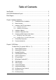
Table of Contents Item Checklist ................................................................................................................. 6 GA-G1975X Motherboard Layout .................................................................................. 7 Block Diagram ................................................................................................................ 8 Chapter 1 Hardware Installation .....................................................................................
Chapter 3 Drivers Installation ...................................................................................... 59 3-1 Install Chipset Drivers .................................................................................... 59 3-2 3-3 3-4 3-5 Software Applications ..................................................................................... 60 Driver CD Information .................................................................................... 60 Hardware Information ..............
Item Checklist IDE Cable x 2 & FDD Cable x 1 Serial ATAII Cable x 4 Serial ATA Power Cable x 2 SATA + Serial ATA Power Cable x 1 2 Ports USB 2.0 Cable x 2 8-Channel Audio Combo kit x 1 2 Ports USB 2.0 + 2 Ports 1394 Cable x 1 I/O Shield DGBR2 Card bracket External Serial ATA Card DGBR2 Card * The items listed above are for reference only, and are subject to change without notice.
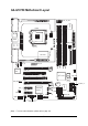
GA-G1975X Motherboard Layout IT8712F ATX_12V_2X4 ATX PWR_FAN LGA775 KB_MS GA-G1975X CPU_FAN LAN USB AUDIO PWR_FAN FDD DDRII4 DDRII1 Broadcom 5789 DDRII3 PCIE_12V CD_IN DDRII2 F_AUDIO Intel ® 975X IDE1 CI PCIE_16_1 PCIE1 Intel ® ICH7R MAIN BIOS SYS_FAN BACKUP BIOS PCIE2 SUR_CEN PCIE_4_1 F_USB1 CREATIVE CA0106 PCIE_4_2 F_USB2 SPDIF_IO F1_1394 COMA PW1 RF_ID (Note) IDE2 Debug LED (Note) For error code information, please refer to page 104.
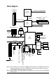
Block Diagram 2 PCI-ECLK (100MHz) CPUCLK+/-(266/200 MHz) LGA775 Processor Host Interface DDRII 888(Note 1) / 667 (Note 2) / 533MHz DIMM PCI Express x16 Intel ® 975X Dual Channel Memory MCHCLK (266/200MHz) LAN1 2 PCI Express x 4 RJ45 Broadcom 5789 PCI-ECLK (100MHz) x4/x1 x4/x1 Dual BIOS x1 PCI Express Bus 4 SATA 3Gb/s Intel® ICH7R ATA33/66/100 IDE Channel PCI Bus TSB43AB23 Floppy IT8211F PCICLK(33MHz) CREATIVE CA0106 COM Port PS/2 KB/Mouse 24MHz Surround Speaker Out Center/Subwoofer S
1-1 English Chapter 1 Hardware Installation Considerations Prior to Installation Preparing Your Computer The motherboard contains numerous delicate electronic circuits and components which can become damaged as a result of electrostatic discharge (ESD). Thus, prior to installation, please follow the instructions below: 1. Please turn off the computer and unplug its power cord. 2. When handling the motherboard, avoid touching any metal leads or connectors. 3.
English 1-2 Feature Summary CPU Front Side Bus Chipset LAN Audio IEEE 1394 Storage O.S Support Memory Expanstion Slots GA-G1975X Motherboard Supports LGA775 Intel ® Pentium ® Processor Extreme Edition/ Pentium ® D / Pentium ® 4 (Note 1) L2 cache varies with CPU Supports 1066/800MHz FSB Northbridge: Intel® 975X Express Chipset Southbridge: Intel ® ICH7R Onboard Broadcom 5789 chip (10/100/1000 Mbit) Onboard CREATIVE CA0106 chip Supports 2 / 4 / 5.1 / 6.
Rear Panel I/O I/O Control Hardware Monitor BIOS Additional Features Bundle Software 1 24-pin ATX power connector 1 8-pin ATX 12V power connector 1 4-pin PCIE 12V power connector 1 floppy connector 2 IDE connectors 4 SATA 3Gb/s connectors 1 CPU fan connector 1 system fan connector 1 power fan connector 1 front panel connector 1 front audio connector 1 CD In connector 1 COMA connector 3 USB 2.0/1.
English Overclocking Form Factor Over Voltage via BIOS (CPU/ DDR II/ PCI-E/ FSB) - CPU Over Voltage : Adjustable CPU voltage at 0.05V (Adjustable range from 1.7500V to 1.0625V) - DIMM Over Voltage : Adjustable DIMM voltage at 0.1V (Adjustable range from +0.1V to +0.7V) - PCI-E Over Voltage : Adjustable DIMM voltage at 0.1V (Adjustable range from +0.1V to +0.7V) - FSB Over Voltage : Adjustable FSB voltage at 0.05V (Adjustable range from +0.05V to +0.
Installation of the CPU and Heatsink Before installing the CPU, please comply with the following conditions: 1. Please make sure that the motherboard supports the CPU. 2. Please take note of the one indented corner of the CPU. If you install the CPU in the wrong direction, the CPU will not insert properly. If this occurs, please change the insert direction of the CPU. 3. Please add an even layer of heat sink paste between the CPU and heatsink. 4.
English 1-3-2 Installation of the Heatsink Male Push Pin The top of Female Push Pin Female Push Pin Fig.1 Please apply an even layer of heatsink paste on the surface of the installed CPU. Fig. 2 (Turning the push pin along the direction of arrow is to remove the heatsink, on the contrary, is to install.) Please note the direction of arrow sign on the male push pin doesn't face inwards before installation. (This instruction is only for Intel boxed fan) Fig.
Installation of Memory Before installing the memory modules, please comply with the following conditions: 1. Please make sure that the memory used is supported by the motherboard. It is recommended that memory of similar capacity, specifications and brand be used. 2. Before installing or removing memory modules, please make sure that the computer power is switched off to prevent hardware damage. 3. Memory modules have a foolproof insertion design. A memory module can be installed in only one direction.
English Dual Channel Memory Configuration The GA-G1975X supports the Dual Channel Technology. After operating the Dual Channel Technology, the bandwidth of Memory Bus will add double. GA-G1975X includes 4 DIMM sockets, and each Channel has two DIMM sockets as following: Channel A : DDR II 1, DDR II 2 Channel B : DDR II 3, DDR II 4 If you want to operate the Dual Channel Technology, please note the following explanations due to the limitation of Intel chipset specifications. 1.
Installation of Expansion Cards You can install your expansion card by following the steps outlined below: 1. Read the related expansion card's instruction document before install the expansion card into the computer. 2. Remove your computer's chassis cover, screws and slot bracket from the computer. 3. Press the expansion card firmly into expansion slot in motherboard. 4. Be sure the metal contacts on the card are indeed seated in the slot. 5.
English 1-6 Configuring a Multi-Graphics Cards System 1-6-1 Configuring a Multi View System This function is supported only on Windows XP operating system. With Multi View technology from GIGABYTE, Dual Graphic enabled motherboards offer multiple display support on up to eight separate monitors. This improves the capabilities and productivity of the user by allowing them to spread multiple windows over eight monitors and view them simultaneously.
To enable CrossFireTM technology on the motherboard, you need one ATI CrossFire TM Edition graphics card (master) and one standard CrossFire TM -ready ATI RADEON graphics card (slave). Before you begin-I. Power Requirements: Before installation, assure that the power supply you use is able to provide sufficient power to fully support an CrossFire configuration and other components in your system. We recommend a power supply that provides at least 20A 12V current.
English 1-7 I/O Back Panel Introduction PS/2 Keyboard and PS/2 Mouse Connector To install a PS/2 port keyboard and mouse, plug the mouse to the upper port (green) and the keyboard to the lower port (purple). Line In Devices like CD-ROM, walkman etc. can be connected to Line In jack. Line Out Connect the stereo speakers, earphone or front surround speakers to this connector. MIC In Microphone can be connected to MIC In jack.
Connectors Introduction English 1-8 3 4 1 2 6 7 13 8 12 19 10 5 21 9 11 18 8 14 20 17 1) 2) 3) 4) 5) 6) 7) 8) 9) 10) 11) ATX_12V_2X4 ATX (Power Connector) PCIE_12V CPU_FAN SYS_FAN PWR_FAN FDD IDE1 / IDE2 SATAII0_1 / SATAII2_3 BATTERY F_PANEL 22 16 15 12) 13) 14) 15) 16) 17) 18) 19) 20) 21) 22) - 21 - F_AUDIO CD_IN SPDIF_IO F_USB1 / F_USB2 / GREEN_USB F1_1394 / F2_1394 RF_ID PWR_LED CI COMA SUR_CEN PW1 / PW2 Hardware Installation
English 1/2) ATX_12V_2X4/ATX (Power Connector) With the use of the power connector, the power supply can supply enough stable power to all the components on the motherboard. Before connecting the power connector, please make sure that all components and devices are properly installed. Align the power connector with its proper location on the motherboard and connect tightly. The ATX 12V (2x4) power connector mainly supplies power to the CPU.
The PCIE_12V power connector supplies extra power to the PCIE x 16 slot. Connect this connector depending on your system requirements. 1 PIin No. 4/5/6) Definition 1 NC 2 GND 3 4 GND +12V CPU_FAN / SYS_FAN / PWR_FAN (Cooler Fan Power Connector) The cooler fan power connector supplies a +12V power voltage via a 3-pin/4-pin (only for CPU_FAN) power connector and possesses a foolproof connection design. Most coolers are designed with color-coded power connector wires.
English 7) FDD (Floppy Connector) The FDD connector is used to connect the FDD cable while the other end of the cable connects to the FDD drive. The types of FDD drives supported are: 360KB, 720KB, 1.2MB, 1.44MB and 2.88MB. Please connect the red power connector wire to the pin1 position. 34 33 2 1 8) IDE1 / IDE2 (IDE Connector) An IDE device connects to the computer via an IDE connector.
SATA 3Gb/s can provide up to 300MB/s transfer rate. Please refer to the BIOS setting for the Serial ATA and install the proper driver in order to work properly. 1 7 7 Pin No. 1 1 Definition GND 2 TXP 3 TXN 4 5 GND RXN 6 RXP 7 GND 10) BATTERY Danger of explosion if battery is incorrectly replaced. Replace only with the same or equivalent type recommended by the manufacturer. Dispose of used batteries according to the manufacturer's instructions. If you want to erase CMOS... 1.
English 11) F_PANEL (Front Panel Jumper) Please connect the power LED, PC speaker, reset switch and power switch etc. of your chassis front panel to the F_PANEL connector according to the pin assignment below.
If you wish to use the front audio function, connect the front panel audio module to this connector. Check the pin assignments carefully while you connect the front panel audio module. Incorrect connection between the module and connector will make the audio device unable to work or even damage it. For optional front panel audio module, please contact your chassis manufacturer. Pin No.
English 14) SPDIF_IO (SPDIF In/Out) The SPDIF output is capable of providing digital audio to external speakers or compressed AC3 data to an external Dolby Digital Decoder. Use this feature only when your stereo system has digital input function. Use SPDIF IN feature only when your device has digital output function. Be careful with the polarity of the SPDIF_IO connector.
Serial interface standard set by Institute of Electrical and Electronics Engineers, which has features like high speed, highbandwidth and hot plug. Be careful with the polarity of the IEEE1394 connector. Check the pin assignment carefully while you connect the IEEE1394 cable, incorrect connection between the cable and connector will make the device unable to work or even damage it. For optional IEEE1394 cable, please contact your local dealer. 2 2 1 F1_1394 10 9 Pin No. 16 F2_1394 15 1 Pin No.
English 18) PWR_LED The PWR_LED connector is connected with the system power indicator to indicate whether the system is on/off. It will blink when the system enters suspend mode. Pin No. 1 Definition 1 2 MPD+ MPD- 3 MPD- 19) CI (Chassis Intrusion, Case Open) This 2-pin connector allows your system to detect if the chassis cover is removed. You can check the "Case Opened" status in BIOS Setup. Pin No.
Be careful with the polarity of the COMA connector. Check the pin assignment carefully while you connect the COMA cable, incorrect connection between the cable and connector will make the device unable to work or even damage it. For optional COMA cable, please contact your local dealer. 2 10 1 9 Pin No.
English 22) PW1 / PW2 C.R.S. (CMOS Reload Switch) allows user to clear the CMOS and reboot the system simultaneously. C.R.S. provides convenient default settings retrieve and jumper-free CMOS reload.
English - 33 - Hardware Installation
English GA-G1975X Motherboard - 34 -
BIOS (Basic Input and Output System) includes a CMOS SETUP utility which allows user to configure required settings or to activate certain system features. The CMOS SETUP saves the configuration in the CMOS SRAM of the motherboard. When the power is turned off, the battery on the motherboard supplies the necessary power to the CMOS SRAM. When the power is turned on, pushing the button during the BIOS POST (Power-On Self Test) will take you to the CMOS SETUP screen.
English : For Boot Menu Select boot sequence for onboard (or add-on cards) device. Award Modular BIOS v6.00PG, An Energy Star Ally Copyright (C) 1984-2004, Award Software, Inc. Intel I975 BIOS for G1975X F1 . . . . :BIOS Setup/Q-Flash, : Xpress Recovery2, For Boot Menu 11/07/2005-I945-6A79HG0GC-00 For Boot Menu Use < > or < > to select a device, then press enter to accept . Press to exit this menu.
English Standard CMOS Features This setup page includes all the items in standard compatible BIOS. Advanced BIOS Features This setup page includes all the items of Award special enhanced features. Integrated Peripherals This setup page includes all onboard peripherals. Power Management Setup This setup page includes all the items of Green function features. PnP/PCI Configuration This setup page includes all the configurations of PCI & PnP ISA resources.
English 2-1 Standard CMOS Features CMOS Setup Utility-Copyright (C) 1984-2005 Award Software Standard CMOS Features ` ` ` ` ` ` Date (mm:dd:yy) Time (hh:mm:ss) Wed, Oct 27 2005 22:31:24 Item Help Menu Level` IDE Channel 0 Master IDE Channel 0 Slave IDE Channel 2 Master IDE Channel 2 Slave IDE Channel 3 Master IDE Channel 3 Slave [None] [None] [None] [None] [None] [None] Change the day, month, year Drive A Drive B Floppy 3 Mode Support [1.44M, 3.
IDE HDD Auto-Detection Press "Enter" to select this option for automatic device detection. Extended IDE Drive SATA IDE devices setup. You can use one of two methods: • Auto Allows BIOS to automatically detect SATA IDE devices during POST(default) • None Select this if no SATA IDE devices are used and the system will skip the automatic detection step and allow for faster system start up. Access Mode Use this to set the access mode for the hard drive.
English Memory The category is display-only which is determined by POST (Power On Self Test) of the BIOS. Base Memory The POST of the BIOS will determine the amount of base (or conventional) memory installed in the system. The value of the base memory is typically 512K for systems with 512K memory installed on the motherboard, or 640K for systems with 640K or more memory installed on the motherboard. Extended Memory The BIOS determines how much extended memory is present during the POST.
Advanced BIOS Features English 2-2 CMOS Setup Utility-Copyright (C) 1984-2005 Award Software Advanced BIOS Features ` Hard Disk Boot Priority BIOS Flash Protection First Boot Device Second Boot Device Third Boot Device Boot Up Floppy Seek Boot Up Num-Lock Password Check Interrupt Mode HDD S.M.A.R.T. Capability CPU Hyper-Threading # Limit CPUID Max.
English Boot Up Floppy Seek Boot Up Floppy SeekDuring POST, BIOS will determine the floppy disk drive installed is 40 or 80 tracks. 360K type is40 tracks 720K, 1.2M and 1.44M are all 80 tracks. Disabled BIOS will not search for the type of floppy disk drive by track number. Note that there will not be any warning message if the drive installed is 360K. (Default value) Enabled BIOS searches for floppy disk drive to determine it is 40 or 80 tracks. Note that BIOS can not tell from 720K, 1.2M or 1.
Enabled Disabled Limit CPUID Maximum value to 3 when use older OS like NT4. Disables CPUID Limit for windows XP.(Default value) No-Execute Memory Protect (Note) Enabled Disabled Enable No-Execute Memory Protect function.(Default value) Disable No-Execute Memory Protect function. CPU Enhanced Halt (C1E) (Note) Enabled Disabled Enable CPU Enhanced Halt (C1E) function.(Default value) Disable CPU Enhanced Halt (C1E) function.
English 2-3 Integrated Peripherals CMOS Setup Utility-Copyright (C) 1984-2005 Award Software Integrated Peripherals On-Chip Primary PCI IDE SATA RAID/AHCI Mode On-Chip SATA Mode x PATA IDE Set to SATA Port 0/2 Set to SATA Port 1/3 Set to USB Controller USB 2.0 Controller USB Keyboard Support USB Mouse Support Legacy USB storage detect Onboard H/W Sound Onboard H/W 1394 Onboard H/W GigaATA Onboard H/W LAN OnBoard LAN Boot ROM Onboard Serial Port 1 i-Lock [Enabled] [Disabled] [Auto] Ch.0 Master/Slave Ch.
Enabled Disabled English USB Controller Enable USB controller. (Default value) Disable USB controller. USB 2.0 Controller Disable this function if you are not using onboard USB 2.0 feature. Enabled Enable USB 2.0 controller. (Default value) Disabled Disable USB 2.0 controller. USB Keyboard Support Enabled Disabled Enable USB keyboard support. Disable USB keyboard support. (Default value) USB Mouse Support Enabled Disabled Enable USB mouse support. Disable USB mouse support.
English 2-4 Power Management Setup CMOS Setup Utility-Copyright (C) 1984-2005 Award Software Power Management Setup ACPI Suspend Type x USB Device Wake-Up From S3 Soft-Off by PWR-BTTN PME Event Wake Up Power On by Ring Resume by Alarm x Date (of Month) Alarm x Time (hh:mm:ss) Alarm Power On By Mouse Power On By Keyboard x KB Power ON Password AC BACK Function [S1(POS)] Enabled [Instant-Off] [Enabled] [Enabled] [Disabled] Everyday 0:0:0 [Disabled] [Disabled] Enter [Soft-Off] KLJI: Move Enter: Select +/-
Password Disabled Keyboard 98 Enter from 1 to 5 characters to set the Keyboard Power On Password. Disabled this function. (Default value) If your keyboard have "POWER Key" button, you can press the key to power on the system. KB Power ON Password When "Power On by Keyboard" set at Password, you can set the password here. Enter Input password (from 1 to 5 characters) and press Enter to set the Keyboard Power On password.
English PCI 1 IRQ Assignment Auto 3,4,5,7,9,10,11,12,14,15 Auto assign IRQ to PCI 1. (Default value) Set IRQ 3,4,5,7,9,10,11,12,14,15 to PCI 1. PCI 2 IRQ Assignment Auto 3,4,5,7,9,10,11,12,14,15 2-6 Auto assign IRQ to PCI 2. (Default value) Set IRQ 3,4,5,7,9,10,11,12,14,15 to PCI 2. PC Health Status CMOS Setup Utility-Copyright (C) 1984-2005 Award Software PC Health Status Reset Case Open Status Case Opened Vcore DDRV +3.
60 o C / 140 o F 70 o C / 158 o F 80 o C / 176 o F 90 o C / 194 o F Disabled English CPU Warning Temperature Monitor CPU temperature at 60o C / 140 oF. Monitor CPU temperature at 70o C / 158 oF. Monitor CPU temperature at 80o C / 176 oF. Monitor CPU temperature at 90o C / 194 oF. Disable this function. (Default value) CPU/POWER/SYSTEM FAN Fail Warning Disabled Enabled Disable fan fail warning function. (Default value) Enable fan fail warning function.
English 2-7 MB Intelligent Tweaker(M.I.T.) CMOS Setup Utility-Copyright (C) 1984-2005 Award Software MB Intelligent Tweaker(M.I.T.) C.A.M. (Note) CPU Clock Ratio (Note) Robust Graphics Booster C.I.A.
Select the options can enhance the VGA graphics card bandwidth to get higher performance. Auto Set Robust Graphics Booster to Auto. (Default value) Fast Set Robust Graphics Booster to Fast. Turbo Set Robust Graphics Booster to Turbo. C.I.A.2 C.I.A.2 (CPU Intelligent Accelerator 2) is designed to detect CPU loading during software program executing, and automatically adjust CPU computing power to maximize system performance. Disabled Disable this function. (Default value) Cruise Set C.I.A.2 to Cruise.
English for FSB(Front Side Bus) frequency=800MHz, 2.00 Memory Frequency = Host clock X 2.00. 2.66 Memory Frequency = Host clock X 2.66. 3.33 Memory Frequency = Host clock X 3.33. 3.00 Memory Frequency = Host clock X 3.00. 4.00 Memory Frequency = Host clock X 4.00. 1.50 Memory Frequency = Host clock X 1.50. 2.0Memory Frequency = Host clock X 2.0-. 2.50 Memory Frequency = Host clock X 2.50. Auto Set Memory frequency by DRAM SPD data.
This feature allows you to select the CAS latency Time, When any DDRII DIMM installed. 5 Set CAS latency Time is 5. 4 Set CAS latency Time is 4. 3 Set CAS latency Time is 3. 6 Set CAS latency Time is 6. Auto Set CAS latency Time automatically. (Default Value) DRAM RAS# to CAS# Delay This feature allows you to set the delay time that from the DRAM RAS# active to CAS#. 2 Set DDRII RAM RAS# to CAS# delay 2 SCLKs. 3 Set DDRII RAM RAS# to CAS# delay 3 SCLKs. 4 Set DDRII RAM RAS# to CAS# delay 4 SCLKs.
English 2-8 Top Performance CMOS Setup Utility-Copyright (C) 1984-2004 Award Software ` ` Select Language Load Fail-Safe Defaults ` ` Standard CMOS Features Advanced BIOS Features Top Performance Integrated Peripherals Power Management Setup Disabled.........................[] ` ` PnP/PCI Configurations Enabled..........................[ ] PC Health Status Set User Password Save & Exit Setup Load Optimized Defaults Set Supervisor Password ` MB Intelligent Tweaker(M.I.T.
English 2-10 Load Fail-Safe Defaults CMOS Setup Utility-Copyright (C) 1984-2005 Award Software ` ` Standard CMOS Features Advanced BIOS Features ` ` Integrated Peripherals Power Management Setup ` ` PnP/PCI Configurations PC Health Status ` MB Intelligent Tweaker(M.I.T.
English 2-12 Set Supervisor/User Password CMOS Setup Utility-Copyright (C) 1984-2005 Award Software ` ` Standard CMOS Features Advanced BIOS Features Select Language Load Fail-Safe Defaults ` ` Integrated Peripherals Power Management Setup Load Optimized Defaults Set Supervisor Password ` ` PnP/PCI Configurations Enter Password: PC Health Status Set User Password Save & Exit Setup ` MB Intelligent Tweaker(M.I.T.
English 2-14 Exit Without Saving CMOS Setup Utility-Copyright (C) 1984-2005 Award Software ` Standard CMOS Features Select Language ` ` Advanced BIOS Features Integrated Peripherals Load Fail-Safe Defaults Load Optimized Defaults ` ` Power Management Setup PnP/PCI Configurations ` ` PC Health Status MB Intelligent Tweaker(M.I.T.
English GA-G1975X Motherboard - 58 -
Pictures below are shown in Windows XP. Insert the driver CD-title that came with your motherboard into your CD-ROM drive, the driver CD-title will auto start and show the installation guide. If not, please double click the CD-ROM device icon in "My computer", and execute the Run.exe. 3-1 Install Chipset Drivers After insert the driver CD, "Xpress Install" will scan automatically the system and then list all the drivers that recommended to install.
English 3-2 Software Applications This page displays all the tools that Gigabyte developed and some free software, you can choose anyone you want and press "install" to install them. 3-3 Driver CD Information This page lists the contents of software and drivers in this CD-title.
Hardware Information English 3-4 This page lists all device you have for this motherboard. 3-5 Contact Us Please see the last page for details.
English GA-G1975X Motherboard - 62 -
4-1 English Chapter 4 Appendix Unique Software Utilities (Not all model support these Unique Software Utilities, please check your MB features.) U-PLUS D.P.S. (Universal Plus Dual Power System) The U-Plus Dual Power System (U-Plus DPS) is a revolutionary eight-phase power circuit built for ultimate system protection. Designed to withstand varying current levels and changes, the U-Plus D.P.S. provides an immensely durable and stable power circuit to the CPU for solid system stability.
English 4-1-1 EasyTune 5 Introduction EasyTune 5 presents the most convenient Windows based system performance enhancement and manageability utility. Featuring several powerful yet easy to use tools such as 1) Overclocking for enhancing system performance, 2) C.I.A. and M.I.B. for special enhancement for CPU and Memory, 3) Smart-Fan control for managing fan speed control of both CPU cooling fan and North-Bridge Chipset cooling fan, 4) PC health for monitoring system status.
Xpress Recovery2 is designed to provide quick backup and restoration of hard disk data. Supporting Microsoft operating systems including Windows XP/2000/NT/98/Me and DOS, and file systems including FAT16, FAT32, and NTFS, Xpress Recovery2 is able to back up data on hard disks on PATA and SATA IDE controllers. After Xpress Recovery2 is executed from CD-ROM for the first time, it will stay permanent in your hard disk.
English The Main Screen of Xpress Recovery2 1. RESTORE: Restore the backed-up data to your hard disk. (This button will not appear if there is no backup file.) 2. BACKUP: Back up data from hard disk. 3. REMOVE: Remove previously-created backup files to release disk space. (This button will not appear if there is no backup file.) 4. REBOOT: Exit the main screen and restart the system. Limitations: 1. 2. 3. Not compatible to Xpress Recovery.
A. What is Dual BIOS Technology? Dual BIOS means that there are two system BIOS (ROM) on the motherboard, one is the Main BIOS and the other is Backup BIOS. Under the normal circumstances, the system works on the Main BIOS. If the Main BIOS is corrupted or damaged, the Backup BIOS can take over while the system is powered on. This means that your PC will still be able to run stably as if nothing has happened in your BIOS. B. How to use Dual BIOS and Q-Flash Utility? a.
English c. Dual BIOS Item explanation: Wide Range Protection: Disable(Default), Enable Status 1: If any failure (ex. Update ESCD failure, checksum error or reset? occurs in the Main BIOS, just before the Operating System is loaded and after the power is on, and that the Wide Range Protection is set to "Enable", the PC will boot from Backup BIOS automatically. Status 2: If the ROM BIOS on peripherals cards(ex. SCSI Cards, LAN Cards,..
Q-Flash TM is a BIOS flash utility embedded in Flash ROM. With this utility, users only have to stay in the BIOS menu when they want to update BIOS. Q-Flash?allows users to flash BIOS without any utility in DOS or Windows. Using Q-FlashTM indicating no more fooling around with any complicated instructions and operating system since it is in the BIOS menu. Please note that because updating BIOS has potential risk, please do it with caution!! We are sorry that Gigabyte Technology Co.
English Entering the Q-FlashTM utility: Step1: To use Q-Flash utility, you must press Del in the boot screen to enter BIOS menu. CMOS Setup Utility-Copyright (C) 1984-2004 Award Software ` ` Standard CMOS Features Advanced BIOS Features Select Language Load Fail-Safe Defaults ` ` Integrated Peripherals Power Management Setup Load Optimized Defaults Set Supervisor Password ` ` PnP/PCI Configurations PC Health Status Set User Password Save & Exit Setup ` MB Intelligent Tweaker(M.I.T.
This section tells you how to update BIOS using the Q-Flash utility. As described in the "Before you begin" section above, you must prepare a floppy disk having the BIOS file for your motherboard and insert it to your computer. If you have already put the floppy disk into your system and have entered the Q-Flash utility, please follow the steps below to flash BIOS. Steps: 1.
English 3. Press Y button on your keyboard after you are sure to update BIOS. Then it will begin to update BIOS. The progress of updating BIOS will be displayed. Please do not take out the floppy disk when it begins flashing BIOS. 4. Press any keys to return to the Q-Flash menu when the BIOS updating procedure is completed. Dual BIOS Utility Boot From......................................... Main Bios Main ROM Type/Size.............................SST 49LF003A Backup ROM Type/Size.........................
Press Del to enter BIOS menu after system reboots. When you are in BIOS menu, move to Load Fail-Safe Defaults item and press Enter to load BIOS Fail-Safe Defaults. Normally the system redetects all devices after BIOS has been upgraded. Therefore, we highly recommend reloading the BIOS defaults after BIOS has been upgraded.
English Exploring the Q-FlashTM utility screen The Q-FlashBIOS utility screen consists of the following key components. Q-FlashTM utility bar Q-Flash Utility V1.30 Flash Type/Size.................................SST 49LF003A Task menu for Q-FlashTM utility Enter : Run Keep DMI Data Enable Update BIOS from Floppy Save BIOS to Floppy KL:Move ESC:Reset 256K F10:Power Off Action bar Task menu for Q-Flash utility: Contains the names of three tasks.
Press Y button on your keyboard after you are sure to update BIOS. Then it will begin to update BIOS. The progress of updating BIOS will be shown at the same time. Q-Flash Utility V1.30 Flash Type/Size.................................SST 49LF003A 256K Keep DMI Data BIOS Enable Updating Now Update BIOS from Floppy >>>>>>>>>>>>>>>>>>>......................... Save BIOS to Floppy EnterDon't : RunTurn OffKL:Move F10:Power Off Power or ResetESC:Reset System 4.
English Method 2 : @BIOSTM Utility If you do not have a DOS startup disk, we recommend that you use the new @BIOS utility. @BIOS allows users to update their BIOS under Windows. Just select the desired @BIOS server to download the latest version of BIOS. Fig 1. Installing the @BIOS utility Fig 2. Installation Complete and Run @BIOS Click Start/ Programs/ GIGABYTE/@BIOS Select @BIOS item than click Install Fig 3. The @BIOS Utility Click "3" Fig 4.
IV. Check out supported motherboard and Flash ROM: In the very beginning, there is "About this program" icon shown in dialog box. It can help you check out which kind of motherboard and which brand of Flash ROM are supported. 2. Note: I. In method I, if it shows two or more motherboard's model names to be selected, please make sure your motherboard's model name again. Selecting wrong model name will cause the system unbooted. II.
English GA-G1975X Motherboard - 78 -
English 4-1-4 Configuring SATA Hard Drive(s) (Controller: Intel ICH7R) To configure SATA hard drive(s), follow the steps below: (1) (2) (3)* (4) Install SATA hard drive(s) in your system. Configure SATA controller mode and boot sequence in BIOS Setup. Configure RAID set in RAID BIOS. Make a floppy disk containing the SATA controller driver. (5) Install the SATA controller driver during OS installation.
English (2) Configuring SATA controller mode and boot sequence in BIOS Setup You have to make sure whether the SATA controller is configured correctly in system BIOS Setup and set BIOS boot sequence for the SATA hard drive(s). Step 1: Turn on your computer and press Del to enter BIOS Setup during POST (Power-On Self Test). If you want to create RAID, set SATA RAID/AHCI Mode under the Integrated Peripherals menu to RAID (Disabled by default).
CMOS Setup Utility-Copyright (C) 1984-2005 Award Software Hard Disk Boot Priority 1. SCSI-0 : 2. Bootable Add-in Cards Intel Volume0 Item Help Menu Level Use < > or < > to select a device, then press <+> to move it up, or <-> to move it down the list. Press to exit this menu. : Move PU/PD/+/-: Change Priority F10: Save ESC: Exit Figure 2 Step 3: Set First Boot Device under the Advanced BIOS Features menu to CD-ROM to boot from CD-ROM after system restarts (Figure 3).
English (3) Configuring RAID set in RAID BIOS Enter the RAID BIOS setup utility to configure a RAID array. Skip this step and proceed to Section 4 if you do not want to create RAID. Step 1: After the POST memory test begins and before the operating system boot begins, look for a message which says "Press to enter Configuration utility" (Figure 4). Press CTRL+ I to enter the RAID BIOS setup utility. Intel(R) Matrix Storage Manager option ROM V5.0.0.
Intel(R) Matrix Storage Manager option ROM V5.0.0.1032 ICH7R wRAID5 Copyright(C) 2003-05 Intel Corporation. All Rights Reversed. [ CREATE VOLUME MENU ] Name : RAID_Volume0 RAID Level : RAID0(Stripe) Disks : Select Disks Strip Size : 128KB Capacity : 223.6 GB Create Volume [ HELP ] RAID0RAID1RAID10RAID5- [ ]-Change Choose the RAID level best suited to your usage model. Data striped across multiple physical drives for performance. Data mirrored across multiple physical drives for redundancy.
English Step 5: After setting all the items above, select Create Volume and press ENTER (Figure 8) to begin the creation of the RAID array. Intel(R) Matrix Storage Manager option ROM V5.0.0.1032 ICH7R wRAID5 Copyright(C) 2003-05 Intel Corporation. All Rights Reversed. [ CREATE VOLUME MENU ] Name : RAID_Volume0 RAID Level : RAID0(Stripe) Disks : Select Disks Strip Size : 128KB Capacity : 223.6 GB Create Volume [ HELP ] Enter the volume capacity.
Intel(R) Matrix Storage Manager option ROM V5.0.0.1032 ICH7R wRAID5 Copyright(C) 2003-05 Intel Corporation. All Rights Reversed. [ MAIN MENU ] 1. Create RAID Volume 2. Delete RAID Volume 3. Reset Disks to Non-RAID 4. Exit [ DISK/VOLUME INFORMATION ] RAID Volumes : ID Name 0 Volume0 Level RAID(Stripe) Physical Disks : Port Driver Model 0 ST3120026AS 1 ST3120026AS Serial # 3JT354CP 3JT329JX [ ]-Select Strip 128KB Size 223.6GB Status Normal Size 111.8GB 111.
English (4) Making a SATA Driver Disk To install operating system onto a serial ATA hard disk successfully, you need to install the SATA controller driver during OS installation. Without the driver, the hard disk may not be recognized during the Windows setup process. First of all, copy the driver for the SATA controller from the motherboard driver CD-ROM to a floppy disk. See the instructions below about how to copy the driver in MS-DOS mode (Note1).
Installing SATA controller driver during OS installation Now that you have prepared the SATA driver disk and configured BIOS settings, you are ready to install Windows 2000/XP onto your SATA hard drive with the SATA driver. The following is an example of Windows XP installation. Step 1: Restart your system to boot from the Windows 2000/XP Setup disk and press F6 as soon as you see the "Press F6 if you need to install a 3rd party SCSI or RAID driver" message (Figure 15).
English Step 3: Use the ARROW keys on your keyboard to select Intel(R) 82801 GR/GH SATA RAID Controller (Desktop ICH7R/DH)* (Figure 17) and press ENTER. Then the system will load the SATA driver from the floppy disk. Windows Setup You have chosen to configure a SCSI Adapter for use with Windows, using a device support disk provided by an adapter manufacturer. Select the SCSI Adapter you want from the following list, or press ESC to return to the previous screen.
WindowsXP Professional Setup Welcome to Setup. This port of the Setup program prepares Microsoft(R) Windows (R) XP to run on your computer. To set up Windows XP now, press ENTER. To repair a Windows XP installation using Recovery Console, press R. To quit Setup without installing Windows XP, press F3. Enter= Continue R=Repair F3=Exit Figure 19 (Note: Each time you add a new hard drive to a RAID array, the RAID driver will have to be installed under Windows once for that hard drive.
English 4-1-5 2- / 4- / 5.1- / 6.1- / 7.1- Channel Audio Function Introduction Please follow the steps below for speakers configurations. (Following pictures are in Windows XP.) For users who wish to configure 4/4.1 channel, 5.1 channel, 6.1 channel, and 7.1 channel speakers, they MUST use the Audio Combo Kit. Accessing Creative Speaker Settings Method One: After installation of the audio driver, you should find a Creative Volume Control icon in your system tray.
We recommend that you use the speaker with amplifier to acquire the best sound effect if the stereo output is applied. STEP 1 : Connect the 2/2.1 channel speakers (headphone) to the Line Out jack. Line Out STEP 2: In the Speaker Selection tab of Creative Speaker Settings, click 2/2.1 Speakers in the Speaker/ Headphone Selection list. After completion, you can click the Channel/Noise button to check whether the speaker selection corresponds to your speaker or headphone configuration.
English STEP 2: Connect the Surround-Kit to the SUR_CEN connector located on the motherboard. Then the installation is completed. 4/4.1 Channel Speaker Configurations Front Speaker Out STEP 1 : Connect the 4/4.1 channel speakers to the Line Out (Front Speaker Out) jack in the back panel and the Rear Speaker Out jack on the Surround Kit. STEP 2: In the Speaker Selection tab of Creative Speaker Settings, click 4/4.1 Speakers in the Speaker/ Headphone Selection list.
Front Speaker Out Rear Speaker C e n t e r / S u b w o o f e r Speaker Out Out STEP 1 : Connect the 5.1 channel speakers to the Line Out (Front Speaker Out) jack in the back panel and the Rear Speaker Out, Center/Subwoofer Speaker Out jacks on the Surround Kit. STEP 2: In the Speaker Selection tab of Creative Speaker Settings, click 5.1 Speakers in the Speaker/Headphone Selection list.
English 7.1 Channel Speaker Configurations Front Speaker Out Rear Speaker Out Side Speaker Out STEP 1 : Connect the 7.1 channel speakers to the Line Out (Front Speaker Out) jack in the back panel and the Rear Speaker Out, Center/Subwoofer Speaker Out, Side Speaker Out jacks on the Surround Kit. Center/Subwoofer Speaker Out STEP 2: In the Speaker Selection tab of Creative Speaker Settings, click 7.1 Speakers in the Speaker/Headphone Selection list.
Connect a decoder to your system through optical cable or coaxial cable. The picture to the right is an example of connecting an optical cable to the optical SPDIF Out jack. 3. In the Speaker Selection tab of Creative Speaker Settings, select the Digital Output Only checkbox to activate digital output. 4. Set the decoder options in Start -> Program -> Creative -> Sound Blaster Live 24-bit -> Device Control to SPDIF Passthrough. Please refer to Page 85. - 95 - English 2.
English 4-1-6 DTS Introduction 1. Introduction In a continuous effort to bring the finest cinematic surround effects to the consumers, Creative has partnered with DTS, Inc to integrate DTS-ES and DTS-Neo:6 into their Sound Blaster line of audio products. This paper will discuss the benefits of having these technologies and how to bring the ultimate entertainment experience out of them via the Creative software applications. 2.
When a 7.1 speaker system is used, a 4-channel or 6-channel audio content can be mapped to the additional speakers. Default is a map to the side speakers. The Creative configuration is completed once the Creative Speaker Settings is set to 6.1 or 7.1 speaker mode. - 97 - Appendix English By default, the on-board Creative audio device provides the decoding. The Use Installed Decoder option will be checked.
English Step 2: Configuring 3rd party SoftDVD players All softDVD players typically have a option to use SPDIF OUT. This option needs to be turned on in conjunction with the Creative settings above for the built-in decoder feature to work. Examples using WinDVD and PowerDVD are illustrated below.
In a case whereby an external hardware decoder (e/g DTS Home Theatre System) is used, the option to use SPDIF Passthrough is to be checked. Encoded audio data will pass through Creative driver without decoding. - 99 - Appendix English 2.
English 2.3 Decoding using SoftDVD player A softDVD player which supports multi-channel playback offers an alternative option to external hardware decoding. Select a 8-channel playback option if a 7.1 speaker system is used. Examples using WinDVD and PowerDVD are illustrated below.
Integrated into Creative's full-featured media player Creative MediaSource, DTS Neo:6 Settings enables users with 5.1 or 6.1 speaker systems to derive five or six full-band channels of audio from twochannel matrix-encoded sources. The result is a richer and more natural aural experience, a luxury that owners of discrete multichannel systems have increasingly come to expect.
English The DTS Neo:6 is located under the time display area in Creative MediaSource Player (version 2.02 and above). It is circled in red below: Neo:6 Mus indicates that Music Mode is enabled while Neo:6 Cin indicates that Cinema Mode is enabled. Note that changes to DTS Neo:6 settings will not take effect on the track that is currently in play. The changes will only take effect from the next track onwards. 4.
Troubleshooting Below is a collection of general asked questions. To check general asked questions based on a specific motherboard model, please log on to http://www.gigabyte.com.tw Question 1: I cannot see some options that were included in previous BIOS after updating BIOS. Why? Answer: Some advanced options are hidden in new BIOS version. Please press Ctrl and F1 keys after entering BIOS menu and you will be able to see these options.
English 4-3 POST Error Code POST (hex) CFh C0h C1h C3h C5h 0h1 03h 05h 07h 08h 0Ah 0Eh 10h 12h 14h 16h 18h 1Bh GA-G1975X Motherboard Description Test CMOS R/W functionality. Early chipset initialization: -Disable shadow RAM -Disable L2 cache (socket 7 or below) -Program basic chipset registers 1. Detect memory -Auto-detection of DRAM size, type and ECC. -Auto-detection of L2 cache (socket 7 or below) 2.
25h 26h 27h 29h 2Bh 2Dh 33h 3Ch 3Eh 40h 43h 47h 49h 4Eh Description Initial EARLY_PM_INIT switch. Load keyboard matrix (notebook platform) HPM initialization (notebook platform) 1. Check validity of RTC value: e.g. a value of 5Ah is an invalid value for RTC minute. 2. Load CMOS settings into BIOS stack. If CMOS checksum fails, use default value instead. 3. Prepare BIOS resource map for PCI & PnP use. If ESCD is valid, take into consideration of the ESCD¡¦s legacy information. 4.
English POST (hex) 50h 52h 55h 57h 59h 5Bh 5Dh 60h 65h 67h 69h 6Bh 6Dh 6Fh 73h 75h 77h 7Ah 7Fh GA-G1975X Motherboard Description Initialize USB Test all memory (clear all extended memory to 0) Display number of processors (multi-processor platform) 1. Display PnP logo 2. Early ISA PnP initialization -Assign CSN to every ISA PnP device. Initialize the combined Trend Anti-Virus code. (Optional Feature) Show message for entering AWDFLASH.EXE from FDD (optional) 1. Initialize Init_Onboard_Super_IO switch.
82h 83h 84h 85h 93h 94h 95h 96h FFh Description 1. Call chipset power management hook. 2. Recover the text fond used by EPA logo (not for full screen logo) 3. If password is set, ask for password. Save all data in stack back to CMOS Initialize ISA PnP boot devices 1. USB final Initialization 2. NET PC: Build SYSID structure 3. Switch screen back to text mode 4. Set up ACPI table at top of memory. 5. Invoke ISA adapter ROMs 6. Assign IRQs to PCI devices 7. Initialize APM 8. Clear noise of IRQs.
English GA-G1975X Motherboard - 108 -
English - 109 - Appendix
English GA-G1975X Motherboard - 110 -
English Contact Us Taiwan (Headquarters) GIGA-BYTE TECHNOLOGY CO., LTD. Address: No.6, Bau Chiang Road, Hsin-Tien, Taipei 231, Japan NIPPON GIGA-BYTE CORPORATION WEB address : http://www.gigabyte.co.jp Singapore Taiwan TEL: +886-2-8912-4888 GIGA-BYTE SINGAPORE PTE. LTD. FAX: +886-2-8912-4003 Tech. Support : Tech. Support : http://tw.giga-byte.com/TechSupport/ServiceCenter.htm http://tw.giga-byte.com/TechSupport/ServiceCenter.htm Non-Tech. Support(Sales/Marketing) : Non-Tech.
English China Russia NINGBO G.B.T. TECH. TRADING CO., LTD. Moscow Representative Office Of GIGA-BYTE Technology Tech. Support : http://tw.giga-byte.com/TechSupport/ServiceCenter.htm Co., Ltd. Tech. Support : Non-Tech. Support(Sales/Marketing) : http://tw.giga-byte.com/TechSupport/ServiceCenter.htm http://ggts.gigabyte.com.tw/nontech.asp Non-Tech. Support(Sales/Marketing) : WEB address : http://www.gigabyte.com.cn Shanghai http://ggts.gigabyte.com.tw/nontech.asp WEB address : http://www.gigabyte.