GA-8I945P Pro/ GA-8I945P-G Intel® Pentium® D / Pentium® 4 LGA775 Processor Motherboard User's Manual Rev. 1005 12ME-8I945PP-1005 * The WEEE marking on the product indicates this product must not be disposed of with user's other household waste and must be handed over to a designated collection point for the recycling of waste electrical and electronic equipment!! * The WEEE marking applies only in European Union's member states.
Motherboard GA-8I945P Pro/GA-8I945P-G Apr. 18, 2005 Motherboard GA-8I945P Pro/GA-8I945P-G Apr.
Copyright © 2005 GIGA-BYTE TECHNOLOGY CO., LTD. All rights reserved. The trademarks mentioned in the manual are legally registered to their respective companies. Notice The written content provided with this product is the property of Gigabyte. No part of this manual may be reproduced, copied, translated, or transmitted in any form or by any means without Gigabyte's prior written permission. Specifications and features are subject to change without prior notice.
Table of Contents GA-8I945P Pro/GA-8I945P-G Motherboard Layout ....................................................... 6 Block Diagram ................................................................................................................ 7 Chapter 1 Hardware Installation ..................................................................................... 9 1-1 1-2 Considerations Prior to Installation .................................................................... 9 Feature Summary .........
Chapter 3 Install Drivers ............................................................................................. 51 3-1 Install Chipset Drivers .................................................................................... 51 3-2 3-3 Software Applications ..................................................................................... 52 Driver CD Information .................................................................................... 52 3-4 3-5 Hardware Information ..........
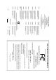
Item Checklist IDE Cable x 2 & FDD Cable x 1 Serial ATAII Cable x 2 Serial ATA Power Cable x 2 2 Ports USB 2.0 + 2 Ports 1394 Cable x 1 I/O Shield * The items listed above are for reference only, and are subject to change without notice.
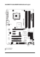
GA-8I945P Pro/GA-8I945P-G Motherboard Layout PWR_FAN CPU_FAN KB_MS ATX_12V COAXIAL LGA775 ATX GA-8I945P (Pro)(-G) COMA LPT OPTICAL LAN AUDIO1 Intel 945P DDRII3 SATAII2 Broadcom 5789 PCIE_1 Main BIOS CODEC ICH7 Back BIOS TSB82AA2 IT8712 PCI2 PCI3 F_USB TSB81BA3 GREEN_USB F1_1394 SPDIF_I CI IT8212 PCI1 SYS_FAN PCIE_2 IDE3 IDE2 ICH7R / SATAII0 CD_IN SATAII3 PCIE_16 DDRII4 IDE1 NB_FAN SATAII1 F_AUDIO DDRII1 AUDIO2 FDD DDRII2 USB R_USB BAT F2_1394 F_PANEL RF_ID PWR
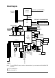
Block Diagram LGA775 Processor PCI-ECLK (100MHz) CPUCLK+/-(133/200/266MHz) Host Interface PCI Express x16 2 PCI Express x1 Intel 945P x1 x1 Dual Channel Memory MCHCLK (133/200/266MHz) 66MHz 33MHz 14.
1-1 English Chapter 1 Hardware Installation Considerations Prior to Installation Preparing Your Computer The motherboard contains numerous delicate electronic circuits and components which can become damaged as a result of electrostatic discharge (ESD). Thus, prior to installation, please follow the instructions below: 1. Please turn off the computer and unplug its power cord. 2. When handling the motherboard, avoid touching any metal leads or connectors. 3.
English 1-2 Feature Summary CPU Chipset Memory Slots IDE Connections FDD Connections Onboard SATA 3Gb/s Peripherals Onboard LAN Supports Intel® Pentium ® D / Pentium® 4 LGA775 CPU(Note 1) Supports 1066/800/533MHz FSB L2 cache varies with CPU Northbridge: Intel® 945P Express Chipset Southbridge: Intel® ICH7R / ICH7 Supported on the Win 2000/XP operating systems 4 DDR II DIMM memory slots (supports up to 4GB memory) (Note 2) Supports 1.
On-Board SATA 3Gb/s RAID On-Board IDE RAID (IDE2, IDE3) I/O Control Hardware Monitor BIOS Additional Features Overclocking Form Factor ALC882 CODEC High Definition Audio Supports 2 / 4 / 6 / 8 channel audio Supports Line In ; Line Out (Front Speaker Out) ; MIC ; Surround Speaker Out (Rear Speaker Out) ; Center/Subwoofer Speaker Out ; Side Speaker Out connection SPDIF In connection SPDIF Out connection (coaxial+optical) CD In Su
English 1-3 Installation of the CPU and Heatsink Before installing the CPU, please comply with the following conditions: 1. Please make sure that the motherboard supports the CPU. 2. Please take note of the one indented corner of the CPU. If you install the CPU in the wrong direction, the CPU will not insert properly. If this occurs, please change the insert direction of the CPU. 3. Please add an even layer of heat sink paste between the CPU and heatsink. 4.
Male Push Pin The top of Female Push Pin Female Push Pin Fig.1 Please apply an even layer of heatsink paste on the surface of the installed CPU. Fig. 2 (Turning the push pin along the direction of arrow is to remove the heatsink, on the contrary, is to install.) Please note the direction of arrow sign on the male push pin doesn't face inwards before installation. (This instruction is only for Intel boxed fan) Fig.
English 1-4 Installing/Removing Cool-Plus (Northbridge Cooling Fan) Fig.1 To attach Cool-Plus to a heatsink, align the extensions on both sides with the grooves in the heatsink as shown. Firmly press down until it snaps into position. Fig.2 Once the fan is properly affixed onto the heatsink, plug the power cable into the NB_FAN connector. Fig.3 Before proceeding, first check to make sure that the fan's power cable is disconnected.
Fig.2 Close the plastic clip at both edges of the DIMM sockets to lock the DIMM module. Reverse the installation steps when you wish to remove the DIMM module. Dual Channel Memory Configuration GA-8I945P (Pro)(-G) supports the Dual Channel Technology. After operating the Dual Channel Technology, the bandwidth of Memory Bus will add double.
English 1-6 Installation of Expansion Cards You can install your expansion card by following the steps outlined below: 1. Read the related expansion card's instruction document before install the expansion card into the computer. 2. Remove your computer's chassis cover, screws and slot bracket from the computer. 3. Press the expansion card firmly into expansion slot in motherboard. 4. Be sure the metal contacts on the card are indeed seated in the slot. 5.
I/O Back Panel Introduction English 1-7 PS/2 Keyboard and PS/2 Mouse Connector To install a PS/2 port keyboard and mouse, plug the mouse to the upper port (green) and the keyboard to the lower port (purple). LPT (Parallel Port) The parallel port allows connection of a printer, scanner and other peripheral devices.
English Center/Subwoofer Speaker Out The default Center/Subwoofer Speaker Out jack. Center/Subwoofer speakers can be connected to Center/Subwoofer Speaker Out jack. Side Speaker Out The default Side Speaker Out jack. Surround side speakers can be connected to Side Speaker Out jack. In addition to the default speakers settings, the ~ audio jacks can be reconfigured to perform different functions via the audio software. Only microphones still MUST be connected to the default Mic In jack ( ) .
ATX_12V/ATX (Power Connector) With the use of the power connector, the power supply can supply enough stable power to all the components on the motherboard. Before connecting the power connector, please make sure that all components and devices are properly installed. Align the power connector with its proper location on the motherboard and connect tightly. The ATX_12V power connector mainly supplies power to the CPU. If the ATX_12V power connector is not connected, the system will not start.
English 3/4/5) CPU_FAN / SYS_FAN / PWR_FAN (Cooler Fan Power Connector) The cooler fan power connector supplies a +12V power voltage via a 3-pin/4-pin (only for CPU_FAN) power connector and possesses a foolproof connection design. Most coolers are designed with color-coded power connector wires. A red power connector wire indicates a positive connection and requires a +12V power voltage. The black connector wire is the ground wire (GND).
The FDD connector is used to connect the FDD cable while the other end of the cable connects to the FDD drive. The types of FDD drives supported are: 360KB, 720KB, 1.2MB, 1.44MB and 2.88MB. Please connect the red power connector wire to the pin1 position. 34 33 2 1 8) IDE1/IDE2/IDE3 (IDE Connector) An IDE device connects to the computer via an IDE connector. One IDE connector can connect to one IDE cable, and the single IDE cable can then connect to two IDE devices (hard drive or optical drive).
English 9) SATAII0/SATAII1/SATAII2/SATAII3 (SATA 3Gb/s Connector) SATA 3Gb/s can provide up to 300MB/s transfer rate. Please refer to the BIOS setting for the Serial ATA II and install the proper driver in order to work properly. 1 7 Pin No. 1 7 1 Definition GND 2 TXP 3 TXN 4 5 GND RXN 6 RXP 7 GND 10) F_AUDIO (Front Audio Connector) This connector supports either HD (High Definition) or AC97 front panel audio module.
PWR_LED is connect with the system power indicator to indicate whether the system is on/off. It will blink when the system enters suspend mode. Pin No. 1 Definition 1 2 MPD+ MPD- 3 MPD- 12) F_PANEL (Front Panel Jumper) Please connect the power LED, PC speaker, reset switch and power switch etc of your chassis front panel to the F_PANEL connector according to the pin assignment below.
English 13) CD_IN (CD IN) Connect CD-ROM or DVD-ROM audio out to the connector. Pin No. 1 1 Definition CD-L 2 GND 3 GND 4 CD-R 14) SPDIF_I (SPDIF In) Use SPDIF IN feature only when your device has digital output function. Be careful with the polarity of the SPDIF_IN connector. Check the pin assignment carefully while you connect the SPDIF cable, incorrect connection between the cable and connector will make the device unable to work or even damage it.
Be careful with the polarity of the front USB connector. Check the pin assignments carefully while you connect the front USB cable, incorrect connection between the cable and connector will make the device unable to work or even damage it. For optional front USB cable, please contact your local dealer. The GREEN_USB connector provides no standby power when system is off and it does not support USB device to wake up from S3 mode.
English 17) RF_ID This connector allows you to connect external devices to use extra function. Check the pin assignments before you connect the external device cable. Please contact your nearest dealer for the optional GIGABYTE external device. Pin No. 1 Definition 1 Power 2 RFID_RI- 3 4 RF_TXD RF_RXD 5 NC 6 GND 18) CI (Chassis Intrusion, Case Open) This 2-pin connector allows your system to detect if the chassis cover is removed. You can check the "Case Opened" status in BIOS Setup. Pin No.
You may clear the CMOS data to its default values by this jumper. To clear CMOS, temporarily short 1-2 pin. Default doesn't include the "Shunter" to prevent from improper use this jumper. 1 1 Open: Normal Short: Clear CMOS 20) BAT(Battery) Danger of explosion if battery is incorrectly replaced. Replace only with the same or equivalent type recommended by the manufacturer. Dispose of used batteries according to the manufacturer's instructions. If you want to erase CMOS... 1.
English GA-8I945P (Pro)(-G) Motherboard - 28 -
BIOS (Basic Input and Output System) includes a CMOS SETUP utility which allows user to configure required settings or to activate certain system features. The CMOS SETUP saves the configuration in the CMOS SRAM of the motherboard. When the power is turned off, the battery on the motherboard supplies the necessary power to the CMOS SRAM. When the power is turned on, pushing the button during the BIOS POST (Power-On Self Test) will take you to the CMOS SETUP screen.
English The Main Menu (For example: BIOS Ver. : GA-8I945P Pro F2a) Once you enter Award BIOS CMOS Setup Utility, the Main Menu (as figure below) will appear on the screen. Use arrow keys to select among the items and press to accept or enter the sub-menu.
Optimized Defaults indicates the value of the system parameters which the system would be in best performance configuration. Set Supervisor Password Change, set, or disable password. It allows you to limit access to the system and Setup, or just to Setup. Set User Password Change, set, or disable password. It allows you to limit access to the system. Save & Exit Setup Save CMOS value settings to CMOS and exit setup. Exit Without Saving Abandon all CMOS value changes and exit setup.
English 2-1 Standard CMOS Features CMOS Setup Utility-Copyright (C) 1984-2005 Award Software Standard CMOS Features Date (mm:dd:yy) Time (hh:mm:ss) ` IDE Channel 0 Master ` IDE Channel 0 Slave Fri, Mar 18 2005 18:25:04 Item Help Menu Level` [None] [None] Change the day, month, year Drive A Drive B Floppy 3 Mode Suport [1.44M, 3.5"] [None] [Disabled] Halt On [All, But Keyboard] Base Memory Extended Memory Total Memory 640K 511M 512M Sun. to Sat. Jan. to Dec.
Drive A / Drive B The category identifies the types of floppy disk drive A or drive B that has been installed in the computer. None No floppy drive installed 360K, 5.25" 5.25 inch PC-type standard drive; 360K byte capacity. 1.2M, 5.25" 5.25 inch AT-type high-density drive; 1.2M byte capacity (3.5 inch when 3 Mode is Enabled). 720K, 3.5" 3.5 inch double-sided drive; 720K byte capacity 1.44M, 3.5" 3.5 inch double-sided drive; 1.44M byte capacity. 2.88M, 3.5" 3.5 inch double-sided drive; 2.88M byte capacity.
English 2-2 Advanced BIOS Features CMOS Setup Utility-Copyright (C) 1984-2005 Award Software Advanced BIOS Features ` Hard Disk Boot Priority First Boot Device Second Boot Device Third Boot Device Password Check # CPU Hyper-Threading Limit CPUID Max.
Enabled Disabled Enables CPU Hyper Threading Feature. Please note that this feature is only working for operating system with multi processors mode supported. (Default value) Disables CPU Hyper Threading. Limit CPUID Max. to 3 Enabled Disabled Limit CPUID Maximum value to 3 when use older OS like NT4. Disables CPUID Limit for windows XP. (Default value) No-Execute Memory Protect (Note) Enabled Disabled Enables No-Execute Memory Protect function.
English 2-3 Integrated Peripherals CMOS Setup Utility-Copyright (C) 1984-2005 Award Software Integrated Peripherals On-Chip Primary PCI IDE On-Chip Secondard PCI IDE SATA RAID/AHCI Mode 1 x On-Chip SATA Mode x PATA IDE Set to SATA Port 0/2 Set to SATA Port 1/3 Set to USB Controller USB 2.
RAID AHCI Disabled Set the onboard SATA controller to RAID mode. (Default value) Set the onboard SATA controller to AHCI mode. Advanced Host Controller Interface (AHCI) is an interface specification that allows the storage driver to enable advanced Serial ATA features such as Native Command Queuing and hot plug. For more details about AHCI, please visit Intel's website. Set the onboard SATA controller to IDE mode. On-Chip SATA Mode Disabled Auto Combined Enhanced Non-Combined Disable this function.
English Onboard H/W 1394 Enabled Disabled Enable onboard IEEE 1394 function.(Default value) Disable this function. Onboard H/W GigaRAID Enabled Disabled Enable Onboard H/W GigaRAID function. (Default value) Disable this function. GigaRAID Function RAID ATA Select onboard GigaRAID chip function as RAID. (Default value) Select onboard GigaRAID chip function asa ATA. Onboard H/W LAN Enabled Disabled Enable Onboard H/W LAN function. (Default value) Disable this function.
Power Management Setup English 2-4 CMOS Setup Utility-Copyright (C) 1984-2005 Award Software Power Management Setup ACPI Suspend Type Soft-Off by PWR-BTTN PME Event Wake Up Power On by Ring Resume by Alarm x Date (of Month) Alarm x Time (hh:mm:ss) Alarm Power On By Mouse Power On By Keyboard x KB Power ON Password AC Back Function KLJI: Move F3: Language1 [S1(POS)] [Instant-off] [Enabled] [Enabled] [Disabled] Everyday 0:0:0 [Disabled] [Disabled] Enter [Soft-Off] Enter: Select +/-/PU/PD: Value F10: Sav
English Power On By Keyboard Password Disabled Keyboard 98 Enter from 1 to 5 characters to set the Keyboard Power On Password. Disabled this function. (Default value) If your keyboard have "POWER Key" button, you can press the key to power on the system. KB Power ON Password When "Power On by Keyboard" set at Password, you can set the password here. Enter Input password (from 1 to 5 characters) and press Enter to set the Keyboard Power On password.
PnP/PCI Configurations CMOS Setup Utility-Copyright (C) 1984-2005 Award Software PnP/PCI Configurations PCI 1 IRQ Assignment PCI 2 IRQ Assignment KLJI: Move F3: Language1 [Auto] [Auto] Enter: Select +/-/PU/PD: Value F10: Save F5: Previous Values F6: Fail-Safe Defaults Item Help Menu Level` ESC: Exit F1: General Help F7: Optimized Defaults PCI 1 IRQ Assignment Auto 3,4,5,7,9,10,11,12,14,15 Auto assign IRQ to PCI 1. (Default value) Set IRQ 3,4,5,7,9,10,11,12,14,15 to PCI 1.
English 2-6 PC Health Status CMOS Setup Utility-Copyright (C) 1984-2005 Award Software PC Health Status Reset Case Open Status Case Opened Vcore DDR18V +3.
Disabled Enabled Disable this function. When this function is enabled, CPU fan will run at different speed depending on CPU temperature. Users can adjust the fan speed with Easy Tune based on their requirements. (Default Value) CPU Smart FAN Mode This option is available only when CPU Smart FAN Control is enabled. Auto BIOS autodetects the type of CPU fan you installed and sets the optimal CPU Smart FAN control mode for it.
English 2-7 MB Intelligent Tweaker(M.I.T.) CMOS Setup Utility-Copyright (C) 1984-2005 Award Software MB Intelligent Tweaker(M.I.T.) CPU Clock Ratio (Note) C.A.M (Note) Robust Graphics Booster C.I.A.
Set C.I.A.2 to Turbo. (Automatically increase CPU frequency(15%,17%) by CPU loading. Full Thrust Set C.I.A.2 to Full Thrust. (Automatically increase CPU frequency(17%, 19%) by CPU loading. Warning: Stability is highly dependent on system components. CPU Host Clock Control Please note that if your system is overclocked and cannot restart, please wait 20secs. for automatic system restart or clear the CMOS setup data and perform a safe restart. Disabled Disable CPU Host Clock Control.
English +0.3V +0.4V +0.5V +0.6V Incorrect using it Set DIMM OverVoltage Control to +0.3V. Set DIMM OverVoltage Control to +0.4V. Set DIMM OverVoltage Control to +0.5V. Set DIMM OverVoltage Control to +0.6V. may cause your system broken. For power End-User use only! PCI-E OverVoltage Control Normal +0.1V +0.2V +0.3V Incorrect using it Set PCI-E OverVoltrage Control to Normal. (Default value) Set PCI-E OverVoltrage Control to +0.1V. Set PCI-E OverVoltrage Control to +0.2V.
Select Language English 2-8 CMOS Setup Utility-Copyright (C) 1984-2005 Award Software ` Standard CMOS Features Select Language 1 ` ` Advanced BIOS Features Integrated Peripherals Load Fail-Safe Defaults Load Optimized Defaults ` ` Power Management Setup PnP/PCI Configurations Set Supervisor Password Set User Password ` ` PC Health Status MB Intelligent Tweaker(M.I.T.
English 2-10 Load Optimized Defaults CMOS Setup Utility-Copyright (C) 1984-2005 Award Software ` ` Standard CMOS Features Advanced BIOS Features ` ` Integrated Peripherals Power Management Setup ` ` PnP/PCI Configurations PC Health Status ` MB Intelligent Tweaker(M.I.T.
English 2-12 Save & Exit Setup CMOS Setup Utility-Copyright (C) 1984-2005 Award Software ` Standard CMOS Features Select Language 1 ` ` Advanced BIOS Features Integrated Peripherals Load Fail-Safe Defaults Load Optimized Defaults ` ` Power Management Setup PnP/PCI Configurations ` ` Set Supervisor Password Set User Password Save to CMOS and EXIT (Y/N)? Y PC Health Status Save & Exit Setup MB Intelligent Tweaker(M.I.T.
English GA-8I945P (Pro)(-G) Motherboard - 50 -
Pictures below are shown in Windows XP. Insert the driver CD-title that came with your motherboard into your CD-ROM drive, the driver CD-title will auto start and show the installation guide. If not, please double click the CD-ROM device icon in "My computer", and execute the Run.exe. 3-1 Install Chipset Drivers After insert the driver CD, "Xpress Install" will scan automatically the system and then list all the drivers that recommended to install.
English 3-2 Software Applications This page displays all the tools that Gigabyte developed and some free software, you can choose anyone you want and press "install" to install them. 3-3 Driver CD Information This page lists the contents of software and drivers in this CD-title.
Hardware Information English 3-4 This page lists all device you have for this motherboard. 3-5 Contact Us Please see the last page for details.
English GA-8I945P (Pro)(-G) Motherboard - 54 -
4-1 English Chapter 4 Appendix Unique Software Utilities (Not all model support these Unique Software Utilities, please check your MB features.) U-PLUS D.P.S. (Universal Plus Dual Power System) The U-Plus Dual Power System (U-Plus DPS) is a revolutionary eight-phase power circuit built for ultimate system protection. Designed to withstand varying current levels and changes, the U-Plus D.P.S. provides an immensely durable and stable power circuit to the CPU for solid system stability.
English 4-1-1 EasyTune 5 Introduction EasyTune 5 presents the most convenient Windows based system performance enhancement and manageability utility. Featuring several powerful yet easy to use tools such as 1) Overclocking for enhancing system performance, 2) C.I.A. and M.I.B. for special enhancement for CPU and Memory, 3) Smart-Fan control for managing fan speed control of both CPU cooling fan and North-Bridge Chipset cooling fan, 4) PC health for monitoring system status.
Xpress Recovery2 is designed to provide quick backup and restoration of hard disk data. Supporting Microsoft operating systems including Windows XP/2000/NT/98/Me and DOS, and file systems including FAT16, FAT32, and NTFS, Xpress Recovery2 is able to back up data on hard disks on PATA and SATA IDE controllers. After Xpress Recovery2 is executed from CD-ROM for the first time, it will stay permanent in your hard disk.
English The Main Screen of Xpress Recovery2 1. RESTORE: Restore the backed-up data to your hard disk. (This button will not appear if there is no backup file.) 2. BACKUP: Back up data from hard disk. 3. REMOVE: Remove previously-created backup files to release disk space. (This button will not appear if there is no backup file.) 4. REBOOT: Exit the main screen and restart the system. Limitations: 1. 2. 3. Not compatible to Xpress Recovery.
A. What is Dual BIOS Technology ? Dual BIOS means that there are two system BIOS (ROM) on the motherboard, one is the Main BIOS and the other is Backup BIOS. Under the normal circumstances, the system works on the Main BIOS. If the Main BIOS is corrupted or damaged, the Backup BIOS can take over while the system is powered on. This means that your PC will still be able to run stably as if nothing has happened in your BIOS. B. How to use Dual BIOS and Q-Flash Utility? a.
English c. Dual BIOS Item explanation: Wide Range Protection: Disable(Default), Enable Status 1: If any failure (ex. Update ESCD failure, checksum error or reset? occurs in the Main BIOS, just before the Operating System is loaded and after the power is on, and that the Wide Range Protection is set to "Enable", the PC will boot from Backup BIOS automatically. Status 2: If the ROM BIOS on peripherals cards(ex. SCSI Cards, LAN Cards,..
Q-Flash TM is a BIOS flash utility embedded in Flash ROM. With this utility, users only have to stay in the BIOS menu when they want to update BIOS. Q-Flash?allows users to flash BIOS without any utility in DOS or Windows. Using Q-FlashTM indicating no more fooling around with any complicated instructions and operating system since it is in the BIOS menu. Please note that because updating BIOS has potential risk, please do it with caution!! We are sorry that Gigabyte Technology Co.
English Entering the Q-FlashTM utility: Step1: To use Q-Flash utility, you must press Del in the boot screen to enter BIOS menu. CMOS Setup Utility-Copyright (C) 1984-2004 Award Software Standard CMOS Features Advanced BIOS Features Select Language Load Fail-Safe Defaults Integrated Peripherals Power Management Setup Load Optimized Defaults Set Supervisor Password PnP/PCI Configurations PC Health Status Set User Password Save & Exit Setup MB Intelligent Tweaker(M.I.T.
This section tells you how to update BIOS using the Q-Flash utility. As described in the "Before you begin" section above, you must prepare a floppy disk having the BIOS file for your motherboard and insert it to your computer. If you have already put the floppy disk into your system and have entered the Q-Flash utility, please follow the steps below to flash BIOS. Steps: 1.
English 3. Press Y button on your keyboard after you are sure to update BIOS. Then it will begin to update BIOS. The progress of updating BIOS will be displayed. Please do not take out the floppy disk when it begins flashing BIOS. 4. Press any keys to return to the Q-Flash menu when the BIOS updating procedure is completed. Dual BIOS Utility Boot From......................................... Main Bios Main ROM Type/Size.............................SST 49LF004A Backup ROM Type/Size.........................
Press Del to enter BIOS menu after system reboots. When you are in BIOS menu, move to Load Fail-Safe Defaults item and press Enter to load BIOS Fail-Safe Defaults. Normally the system redetects all devices after BIOS has been upgraded. Therefore, we highly recommend reloading the BIOS defaults after BIOS has been upgraded.
English Exploring the Q-FlashTM utility screen The Q-FlashBIOS utility screen consists of the following key components. Q-FlashTM utility bar Q-Flash Utility V1.30 Flash Type/Size.................................SST 49LF003A Task menu for Q-FlashTM utility Enter : Run Keep DMI Data Enable Update BIOS from Floppy Save BIOS to Floppy :Move ESC:Reset 256K F10:Power Off Action bar Task menu for Q-Flash utility: Contains the names of three tasks.
Press Y button on your keyboard after you are sure to update BIOS. Then it will begin to update BIOS. The progress of updating BIOS will be shown at the same time. Q-Flash Utility V1.30 Flash Type/Size.................................SST 49LF002A 256K Keep DMI Data BIOS Enable Updating Now Update BIOS from Floppy >>>>>>>>>>>>>>>>>>>......................... Save BIOS to Floppy EnterDon't : RunTurn Off Power :Moveor ResetESC:Reset F10:Power Off System 4.
English Method 2 : @BIOSTM Utility If you do not have a DOS startup disk, we recommend that you use the new @BIOS utility. @BIOS allows users to update their BIOS under Windows. Just select the desired @BIOS server to download the latest version of BIOS. Fig 1. Installing the @BIOS utility Fig 2. Installation Complete and Run @BIOS Click Sart/ Programs/ GIGABYTE/@BIOS Select @BIOS item than click Install Fig 3. The @BIOS Utility Click " " Fig 4.
IV. Check out supported motherboard and Flash ROM: In the very beginning, there is "About this program" icon shown in dialog box. It can help you check out which kind of motherboard and which brand of Flash ROM are supported. 2. Note: I. In method I, if it shows two or more motherboard's model names to be selected, please make sure your motherboard's model name again. Selecting wrong model name will cause the system unbooted. II.
English 4-1-4 Serial ATA BIOS Setting Utility Introduction RAID Levels RAID (Redundant Array of Independent Disks) is a method of combining two hard disk drives into one logical unit. The advantage of an Array is to provide better performance or data fault tolerance. Fault tolerance is achieved through data redundant operation, where if one drives fails, a mirrored copy of the data can be found on another drive. This can prevent data loss if the operating system fails or hangs.
Configuring the Intel RAID BIOS The Intel RAID BIOS setup lets you choose the RAID array type and which hard drives you want to make part of the array. Entering the RAID BIOS Setup 1. After rebooting your computer, wait until you see the RAID software prompting you to press Ctrl + I. The RAID prompt appears as part of the system POST and boot process prior to loading the OS. You have a few seconds to press Ctrl + I before the window disappears. Intel(R) Matrix Storage Manager option ROM V5.0.0.
English Create RAID Volume Press Enter under Create RAID Volume to set up RAID. Intel(R) Matrix Storage Manager option ROM V5.0.0.1011 ICH7R wRAID5 Copyright(C) 2003-04 Intel Corporation. All Rights Reversed. [ CREATE VOLUME MENU ] Name : RAID_Volume0 RAID Level : RAID0(Stripe) Disks : Select Disks Strip Size : 128KB Capacity : 223.5 GB Create Volume [ HELP ] Enter a string between 1 and 16 characters in length that can be used to uniquely identify the RAID volume.
Intel(R) Matrix Storage Manager option ROM V5.0.0.1011 ICH7R wRAID5 Copyright(C) 2003-04 Intel Corporation. All Rights Reversed. [ CREATE VOLUME MENU ] Name : RAID_Volume0 RAID Level : RAID0(Stripe) Disks : Select Disks Strip Size : 128KB Capacity : 223.5 GB Create Volume [ HELP ] The following are typical values: RAID 0 - 128KB RAID 1 - 64KB RAID 5 - 64KB [ ]-Change [TAB]-Next [ESC]-Previous Menu [ENTER]-Select Intel(R) Matrix Storage Manager option ROM V5.0.0.
English Press Enter under the Create Volume item. Intel(R) Matrix Storage Manager option ROM V5.0.0.1011 ICH7R wRAID5 Copyright(C) 2003-04 Intel Corporation. All Rights Reversed. [ CREATE VOLUME MENU ] Name : RAID_Volume0 RAID Level : RAID0(Stripe) Disks : Select Disks Strip Size : 128KB Capacity : 223.
Intel(R) Matrix Storage Manager option ROM V5.0.0.1011 ICH7R wRAID5 Copyright(C) 2003-04 Intel Corporation. All Rights Reversed. [ MAIN MENU ] 1. Create RAID Volume 2. Delete RAID Volume 3. Reset Disks to Non-RAID 4. Exit [ DISK/VOLUME INFORMATION ] RAID Volumes : ID Name 0 RAID_Volume0 Level RAID(Stripe) Physical Disks : Port Driver Model 0 ST3120026AS 1 ST3120026AS Serial # 3JT329JX 3JT354CP [ ]-Select Strip 128KB Size 223.5GB Status Normal Size 111.7GB 111.
English Installing the RAID drivers To install operating system onto a serial ATA hard disk successfully, you need to install the SATA controller driver during OS installation. Without the driver, the hard disk may not be recognized during the Windows setup process. First of all, copy the driver for the SATA controller from the motherboard driver CD-ROM to a floppy disk. See the instructions below about how to copy the driver in MS-DOS mode (Note1).
This motherboard provide 6 audio connector. You are able to use 2-/4-/6/8-channnels audio feature by audio software selection. The default speaker settings for the 6 audio jacks are as shown in the picture to the right. The jack retasking capability supported by HD Audio allows users to Line In Rear Speaker Out change the function for each audio jack by the audio Line Out Center/Subwoofer software provided.
English STEP 3: After a speaker or headphone is plugged into the rear Line Out jack, a small window will pop up and ask you what type of equipment is connected. Choose Headphone or Line Out depending on the device connected and click OK. The 2-channel audio setup is completed. 4 Channel Audio Setup STEP 1 : After installation of the audio driver, you should find an Audio Manager icon in your system tray (you can also find the icon in Control Panel). Double-click the icon to open the Audio Control Panel.
English 6 Channel Audio Setup STEP 1 : After installation of the audio driver, you should find an Audio Manager icon in your system tray (you can also find the icon in Control Panel). Double-click the icon to open the Audio Control Panel. STEP 2: In the Audio Control Panel, click the Audio I/O tab. In the upper left list, click 6CH Speaker. STEP 3: After plugging in 6-channel speakers to the rear speaker jacks, a small window will pop up and ask you what type of equipment is connected.
English STEP 2: In the Audio Control Panel, click the Audio I/O tab. In the upper left list, click 8CH Speaker. STEP 3: After plugging in 8-channel speakers to the rear speaker jacks, a small window will pop up and ask you what type of equipment is connected. Choose a device depending on the type of speaker connected (8-channel audio consists of Front Speaker Out (Line Out), Rear Speaker Out, Center/Subwoofer Speaker Out, and Side Speaker Out) then click OK. The 8channel audio setup is completed.
Troubleshooting Below is a collection of general asked questions. To check general asked questions based on a specific motherboard model, please log on to http://www.gigabyte.com.tw Question 1: I cannot see some options that were included in previous BIOS after updating BIOS. Why? Answer: Some advanced options are hidden in new BIOS version. Please press Ctrl and F1 keys after entering BIOS menu and you will be able to see these options.
English GA-8I945P (Pro)(-G) Motherboard - 82 -
English - 83 - Appendix
English GA-8I945P (Pro)(-G) Motherboard - 84 -
English - 85 - Appendix
English GA-8I945P (Pro)(-G) Motherboard - 86 -
English Contact Us Taiwan (Headquarters) Japan GIGA-BYTE TECHNOLOGY CO., LTD. NIPPON GIGA-BYTE CORPORATION Address: No.6, Bau Chiang Road, Hsin-Tien, Taipei 231, Taiwan WEB address : http://www.gigabyte.co.jp Singapore TEL: +886-2-8912-4888 GIGA-BYTE SINGAPORE PTE. LTD. FAX: +886-2-8912-4003 Tech. Support : Tech. Support : http://tw.giga-byte.com/TechSupport/ServiceCenter.htm http://tw.giga-byte.com/TechSupport/ServiceCenter.htm Non-Tech. Support(Sales/Marketing) : Non-Tech.
English China Russia NINGBO G.B.T. TECH. TRADING CO., LTD. Moscow Representative Office Of GIGA-BYTE Technology Co., Tech. Support : http://tw.giga-byte.com/TechSupport/ServiceCenter.htm Ltd. Tech. Support : Non-Tech. Support(Sales/Marketing) : http://tw.giga-byte.com/TechSupport/ServiceCenter.htm http://ggts.gigabyte.com.tw/nontech.asp Non-Tech. Support(Sales/Marketing) : WEB address : http://www.gigabyte.com.cn Shanghai http://ggts.gigabyte.com.tw/nontech.asp WEB address : http://www.gigabyte.