GA-8I915P Series Intel® Pentium® 4 LGA775 Processor Motherboard User's Manual Rev.
Motherboard GA-8I915P/GA-8I915P Ultra/GA-8I915P Pro/GA-8I915P-G Aug.17, 2004 Motherboard GA-8I915P/GA-8I915P Ultra/ GA-8I915P Pro/GA-8I915P-G Aug.
Copyright © 2004 GIGA-BYTE TECHNOLOGY CO., LTD. All rights reserved. The trademarks mentioned in the manual are legally registered to their respective companies. Notice The written content provided with this product is the property of Gigabyte. No part of this manual may be reproduced, copied, translated, or transmitted in any form or by any means without Gigabyte's prior written permission. Specifications and features are subject to change without prior notice.
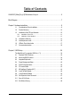
Table of Contents GA-8I915P (Ultra)(Pro)(-G) Motherboard Layout ........................................................ 6 Block Diagram ........................................................................................................... 7 Chapter 1 Hardware Installation .................................................................................. 9 1-1 Considerations Prior to Installation .........................................................................9 1-2 1-3 Feature Summary .....
Chapter 3 Install Drivers ......................................................................................... 49 3-1 3-2 3-3 3-4 3-5 Install Chipset Drivers ..........................................................................................49 Software Applications ............................................................................................50 Driver CD Information ...........................................................................................50 Hardware Information .
GA-8I915P (Ultra)(Pro)(-G) Motherboard Layout DDR4 LG A 775 DDR3 A TX_12V SP DIF_O UT DDR2 DDR1 PWR_FA N CPU_FAN KB_MS LAN USB USB GA-8I915P (Ultra)(Pro)(-G) COMA LPT ATX SP DIF_IN A UDIO 1 I ntel 915P 8001 IDE1 AZALIA_FP CD_IN Marv ell A UDIO 2 NB_FAN P CI E _16 FDD S_AT A4 P CI E_1 CODEC S_AT A3 I ntel I CH 6 BAT P CI E_2 S_AT A2 S_AT A1 BACK MAIN BIOS IT8712 PCI1 TS B43A B23 PCI2 IR IDE3 IDE2 F1_1 394 F_U SB 2 SYS_FAN F_PAN EL F_U SB 1 F2_1 394 Only for GA-8I915
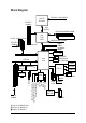
Block Diagram PCI-ECLK (100MHz) CPUCLK+/-(200/133MHz) LGA775 Processor Host Interface Intel 915P MCH 3 PCI E xpressx 1 Ports PCI-ECLK (100MHz) DDR 400/333/266MHz DIMM Dual Channel Memory MCHCLK (200/133M Hz) 66MHz 33MHz 14.318MHz 48MHz PCI Express x16 Dual BIOS PCI Express x1 Bus 4 Serial ATA ATA33/66/100 IDE1 Channels Intel ICH6 PCI Bus Floppy LPT Port TSB43AB23 RJ45 IT 8712 3 IEEE1394 CODEC 2 PCI PCICLK (33MHz) Only for GA-8I915P Ultra. Only for GA-8I915P Pro. Only for GA-8I915P-G.
-8-
1-1 English Chapter 1 Hardware Installation Considerations Prior to Installation Preparing Your Computer The motherboard contains numerous delicate electronic circuits and components which can become damaged as a result of electrostatic discharge (ESD). Thus, prior to installation, please follow the instructions below: 1. Please turn off the computer and unplug its power cord. 2. When handling the motherboard, avoid touching any metal leads or connectors. 3.
English 1-2 Feature Summary CPU Motherboard Chipset Memory Slots IDE Connections w w w w w w w w w w w w w w FDD Connections Onboard SATA Peripherals Onboard LAN Onboard Audio w w w w w w w w w w w w w w w w w w Supports the latest Intel® Pentium ® 4 LGA775 CPU Supports 800/533MHz FSB L2 cache varies with CPU GA-8I915P Series Motherboard: GA-8I915P Ultra/GA-8I915P Pro/GA-8I915P-G/GA-8I915P Northbridge: Intel® 915P Express Chipset Southbridge: Intel® ICH6 4 DDR DIMM memory slots (supports up to 4G
w w w w w w w w w w I/O Control Hardware M onitor BIOS Additional Features Overclocking Form Factor w w w w w w w w w w w w w Onboard GigaRAID IT8212 chipset Supports disk striping (RAID 0) or disk m irroring (RAID 1) or striping + mirroring (RAID 0 + RAID 1) Supports JBOD function Supports concurrent dual ATA133 IDE controller operation Supports ATAPI m ode for HDD Supports IDE bus master operation Supports ATA133/RAID m ode switch by BIOS Displays status and error checking m essages during boot-up Mir
English 1-3 Installation of the CPU and Heatsink Before installing the CPU, please comply with the following conditions: 1. Please make sure that the motherboard supports the CPU. 2. Please take note of the one indented corner of the CPU. If you install the CPU in the wrong direction, the CPU will not insert properly. If this occurs, please change the insert direction of the CPU. 3. Please add an even layer of heat sink paste between the CPU and heatsink. 4.
Male Push P in The top of Female P ush P in Female P ush Pin Fig.1 Please apply an even layer of heatsink paste on the surface of the installed CPU. Fig. 2 (Turning the push pin along the direction of arrow is to rem ove the heatsink, on the contrary, is to install.) Please note the direction of arrow sign on the m ale push pin doesn't face inwards before installation. (This instruction is only for Intel boxed fan) Fig.
English 1-4 Installation of Memory Before installing the memory modules, please comply with the following conditions: 1. Please make sure that the memory used is supported by the motherboard. It is recommended that memory of si mi lar capaci ty , speci fi cati ons and br and be used. 2 . Before i ns tall ing or r emov ing memor y modules, pleas e mak e sure t hat the comput er pow er i s sw i t ched off t o prev ent har dw are damage. 3. Memory modules have a foolproof insertion design.
We'll strongly recom mend our user to slot two DDR memory m odules into the DIMMs with the same color in order for Dual Channel Technology to work. The following table is for Dual Channel Technology com bination: (DS: Double Side, SS: Single Side) 2 memory modules 4 memory modules DDR1 DS/SS X DS/SS DDR 2 X DS/SS DS/SS - 15 - DDR3 DS/SS X DS/SS DDR4 X DS/SS DS/SS Hardware Installation English Dual Channel DDR GA-8I915P Series supports the Dual Channel Technology.
English 1-5 Install expansion cards You can install your expansion card by following the steps outlined below: 1. Read the related expansion card's instruction document before install the expansion card into the computer. 2. Remove your computer's chassis cover, screws and slot bracket from the computer. 3. Press the expansion card firmly into expansion slot in motherboard. 4. Be sure the metal contacts on the card are indeed seated in the slot. 5.
I/O Back Panel Introduction English 1-6 PS/2 Keyboard and PS/2 Mouse Connector To install a PS/2 port keyboard and mouse, plug the mouse to the upper port (green) and the keyboard to the lower port (purple). Parallel Port The parallel port allows connection of a printer, scanner and other peripheral devices. SPDIF_O (SPDIF Out) The SPDIF output is capable of providing digital audio to external speakers or compressed AC3 data to an external Dolby Digital Decoder.
English Back Surround Speaker Out Connect the back surround channels to this connector. Center/Subwoofer Speaker Out Connect the Center/Subwoofer channels to this connector. Surround Speaker Out Connect the surround channels to this connector. You can use audio software to configure 2-/4-/5.1-/7.1-channel audio functioning.
ATX_12V/ATX (Power Connector) With the use of the power connector, the power supply can supply enough stable power to all the components on the motherboard. Before connecting the power connector, please make sure that all components and devices are properly installed. Align the power connector with its proper location on the motherboard and connect tightly. The ATX_12V power connector mainly supplies power to the CPU. If the ATX_12V power connector is not connected, the system will not start.
English 3/4/5) CPU_FAN / SYS_FAN / PWR_FAN (Cooler Fan Power Connector) The cooler fan power connector supplies a +12V power voltage via a 3-pin/4-pin (only for CPU_FAN) power connector and possesses a foolproof connection design. Most coolers are designed with color-coded power connector wires. A red power connector wire indicates a positive connection and requires a +12V power voltage. The black connector wire is the ground wire (GND).
The FDD connector is used to connect the FDD cable while the other end of the cable connects to the FDD drive. The types of FDD drives supported are:360KB, 720KB, 1.2MB, 1.44MB and 2.88MB. Please connect the red power connector wire to the pin1 position. 34 2 33 1 8/9) IDE1/IDE2/IDE3 (IDE Connector) An IDE device connects to the com puter via an IDE connector. One IDE connector can connect to one IDE cable, and the single IDE cable can then connect to two IDE devices (hard drive or optical drive).
English 10) S_ATA1/S_ATA2/S_ATA3/S_ATA4(Serial ATA Connector, Controlled by ICH6) Serial ATA can provide 150MB/s transfer rate. Please refer to the BIOS setting for the Serial ATA and install the proper driver in order to work properly. 7 1 Pin No. 1 2 3 4 5 6 7 Definition GND TXP TXN GND RXN RXP GND 11) PWR_LED PWR_LED is connect with the system power indicator to indicate whether the system is on/off. It will blink when the system enters suspend mode.
Please connect the power LED, PC peaker, reset switch and power switch etc of your chassis front panel to the F_PANEL connector according to the pin assignment below.
English 13) AZALIA_FP (Front Audio Panel Connector) Please make sure the pin assigment on the cable is the same as the pin assigment on the MB header. To find out if the chassis you are buying support front audio panel connector, please contact your dealer. 10 9 2 1 Pin No. 1 2 3 4 5 6 7 8 9 10 Definition MIC2_L GND MIC2_R -ACZ_DET Line2_R FSENSE1 FAUOIO_JD No Pin LINE2_L FSENSE2 Pin No.
Be careful with the polarity of the front USB connector. Check the pin assignment carefully while you connect the front USB cable, incorrect connection between the cable and connector will make the device unable to work or even damage it. For optional front USB cable, please contact your local dealer. The "USB Device Wake up From S3" is only supported by rear USB ports. 2 10 1 9 Pin No.
English 17) IR Be careful with the polarity of the IR connector while you connect the IR. Please contact you nearest dealer for optional IR device. Pin No. 1 2 3 4 5 1 Definition VCC No Pin IR RX GND IR TX 18) CLR_CMOS (Clear CMOS) You may clear the CMOS data to its default values by this jumper. To clear CMOS, temporarily short 1-2 pin. Default doesn't include the "Shunter" to prevent from improper use this jumper.
English 19) BAT(Battery) Danger of explosion if battery is incorrectly replaced. Replace only with the same or equivalent type recommended bythe manufacturer. Dispose of used batteries according to the manufacturer's instructions. If you want to erase CM OS... 1.Turn OFF the computer and unplug the power cord. 2.Remove the battery, wait for 30 second. 3.Re-install the battery. 4.Plug the power cord and turn ON the computer.
English GA-8I915P Series Motherboard - 28 -
BIOS (Basic Input and Output Sy stem) includes a CMOS SETUP utility w hich allow s user to configure required settings or to activ ate certain sy stem features. The CMOS SETUP sav es the configuration in the CMOS SRAM of the motherboard. When the pow er is turned off, the battery on the motherboard supplies the necessary pow er to the CMOS SRAM. When the pow er is turned on, pushing the button during the BIOS POST (Pow er-On Self Test) w ill take y ou to the CMOS SETUP screen.
English The Main Menu (For example: BIOS Ver. : F1) Once y ou enter Aw ard BIOS C MOS Setup Utility , the Main Menu (as figure below ) w ill appear on the screen. Use arrow key s to select among the items and press to accept or enter the sub-menu. CMOS Setup Utility -Cop y right (C) 198 4-2004 Award Software } } } } } } } Stan dard CM OS Features Advanc ed BIOS Fe atures IntegratedPeripherals Power Manag ement Setup PnP/PCI Configur ations PC H ealth Status MB In telligent Tweaker(M. I.T.
n Load O ptimized Defaults Optimized Defaults indicates the v alue of the sy stem parameters w hich performance c onfiguration. n Set Supervisor Password Change, set, or disable passw ord. It allows y ou to limit access to the sy n Set User Password Change, set, or disable passw ord. It allow s y ou to lim it access to the sy n Save & Exit S etup Sav e CMOS v alue settings to CMOS and ex it setup. n Exit Without S aving Abandon all CMOS v alue changes and ex it setup.
English 2-1 Standard CMOS Features CMOS Setup Utility -Cop y right (C) 198 4-2004 Award Software Stan dard CM OS Features Date(mm:dd:y y ) Time (hh:mm:ss) } IDE Channel 0 M aster } IDE Channel 0 Slave Mon, Ma y 17 2004 22:3 1:24 Item Help Menu Level} [None] [None] Change the day, month, y ear Drive A Driv e B Flopp y 3 Mode Suport [1.44M, 3.5"] [None] [Disabled] Halt On [All, But Key b oard] BaseMemory ExtendedMemory Total Memory 640K 511M 512M Su n. to Sa t. Jan. to Dec.
The category identifies the ty pes of floppy dis k driv e A or driv e B that has been installed in the computer. None No floppy driv e installed 360K, 5.25" 5.25 inch PC-ty pe standard drive; 360K by te capacity . 1.2M, 5.25" 5.25 inch AT-ty pe high-density driv e; 1.2M by te capacity (3.5 inch w hen 3 Mode is Enabled). 720K, 3.5" 3.5 inch double-sided driv e; 720K by te capacity 1.44M, 3.5" 3.5 inch double-sided driv e; 1.44M by te capacity . 2.88M, 3.5" 3.5 inch double-sided driv e; 2.88M by te capacity .
English 2-2 Advanced BIOS Features CMOS Setup Utility -Cop y right (C) 198 4-2004 Award Software Advanc ed BIOS Fe atures } Hard Disk Bo ot Prio rity First Boot De vice Second Bo ot Device Third Boo t Device Pass word Check # CPU H y per-Thre ading Limit CPUID Max.
Enabled Disabled Enables CPU Hy per Threading Feature. Please note that this feature is only working for operating sy stem w ith multi processors mode supported. (Default v alue) Disables CPU Hy per Threading. Limit CPUID Max. to 3 Enabled Disabled Limit CPUID Max imum v alue to 3 w hen use older OS like NT4. (Default v alue) Disables CPUID Limit for w indow s XP.
English 2-3 Integrated Peripherals CMOS Setup Utility -Cop y right (C) 198 4-2004 Award Software IntegratedPeripherals On-Chip Prim ary PCI IDE On-Ch ip SATA Mode x PATA IDE Se t to SATA Port 0/2 Set to SATA Port 1/3 Set to USB Contro ller USB 2 .
Disabled Auto Combined Enhanced Non-Combined Disable this function. BIOS w ill auto detect. (Default v alue) Set On-Chip SATA mode to Combined, y ou c an use up to 4 HDDs on the m otherboard; 2 for SATA and the other for PATA IDE. Set On-Chip SATA mode to Enhanced, the motherboard allow s up to 6 HDDs to use. Set On-Chip SATA mode to Non-Com bined, SATA w ill be simulated to PATA mode. PATA IDE Set to Ch.1Master/Slav e Ch.0Master/Slav e Set PATA IDE to Ch. 1 Master/Slav e.
English Onboard H/W GigaRAID Enabled Disabled Enable Onboard H/W GigaRAID function. (Default v alue) Disable this function. GigaRAID Function RAID ATA A Selec t onboard GigaRAID chip function as RAID. (Default v alue) Selec t onboard GigaRAID chip function asa ATA. Onboard H/W LAN Enabled Disabled Enable Onboard H/W LAN function. (Default v alue) Disable this function. Onboard LAN Boot ROM This function decide w hether to inv oke the boot ROM of the onboard LAN chip. Enabled Enable this func tion.
Disabled 378/ IRQ7 278/ IRQ5 3BC/ IRQ7 English Onboard Parallel port Disable onboard LPT port. Enable onboard LPT port and address is 378/IRQ7. (Default v alue) Enable onboard LPT port and address is 278/ IRQ5. Enable onboard LPT port and address is 3BC/ IRQ7. Paral lel Port Mode SPP EPP ECP ECP+EPP Using Using Using Using Parallel Parallel Parallel Parallel port as port as port as port as Standard Parallel Port. (Default v alue) Enhanced Parallel Port. Ex tended Capabilities Port. ECP & EPP mode.
English 2-4 Power Management Setup CMOS Setup Utility -Cop y right (C) 198 4-2004 Award Software Power Manag ement Setup ACPI Suspend Ty pe Soft- Off by PWR-BTTN PME E vent Wake Up Power On by Ring Resumeby Alarm x Date (of Month) Alarm x Time(hh:mm:ss) Alarm Power On By Mouse Power On By Key board x KB Power O N Password AC Back Func tion higf: M ove Enter: Select F5: P revious Values [S1(P OS)] [Instan t-off] [Enabled] [Enabled] [Disabled] Every day 0: 0: 0 [Disabled] [Disabled] Enter [Soft-Off] +/-
Pass w ord Disabled Key board 98 Enter from 1 to 5 charac ters to set the Key board Pow er On Pass w ord. Disabled this function. (Default v alue) If y our key board hav e "POWER Key " button, y ou can press the k ey to pow er on the system. KB Power ON Password When "Pow er On by Key board" set at Passw ord, y ou can set the passw ord here. Enter Input passw ord (from 1 to 5 characters) and press Enter to set the Key board Pow erOn passw ord.
English 2-5 PnP/PCI Configurations CMOS Setup Utility -Cop y right (C) 198 4-2004 Award Software PnP/PCI Configur ations PCI 1 IRQ Assignment PCI 2 IRQ Assignment higf: M ove Enter: Select F5: P revious Values [Auto] [Auto] +/-/PU/P D:Value F6: Fa il-Safe De fault Item Help Menu Level} F10: Save ESC: Ex it F1: Gene ral Help F7: Optimized Defa ults PCI 1 IRQ Assignment Auto 3,4,5,7,9,10,11,12,14,15 Auto assign IRQ to PCI 1. (Default v alue) Set IRQ 3,4,5,7,9,10,11,12,14,15 to PCI 1.
PC Health Status CMOS Setup Utility -Cop y right (C) 198 4-2004 Award Software PC H ealth Status Vcore DDR25V +3.
English CPU FAN PIN Type In order to make "CPU Smart FAN Control" function w ork properly , please set the pin number according to the CPU FAN that y ou used. 3 PIN Set C PU FAN PIN Ty pe to 3 pin. (Default v alue) 4 PIN Set C PU FAN PIN Ty pe to 4 pin. 2-7 MB Intelligent Tweaker(M.I.T.) CMOS Setup Utility -Cop y right (C) 198 4-2004 Award Software MB In telligent Tweaker(M. I.T.) CPU Clock Ratio C.I. A.
Pleas e note that if y our sy stem is ov ercloc ked and c annot restart, please w ait 20secs. for automatic s y stem res tart or c lear the C MOS setup data and perform a safe res tart. Disabled Disable CPU Host Clock C ontrol. (Default v alue) Enabled Enable CPU Host Clock Control. CPU Host Frequency (Mhz) 100MHz ~ 355MHz Set CPU Host Clock from 100MHz to 355MHz. If y ou use FSB533 Pentium 4 processor, please set "CPU Clock" to 133MHz.
English 2-8 Load Fail-Safe Defaults CMOS Setup Utility -Cop y right (C) 198 4-2004 Award Software } } } } } } } Stan dard CM OS Features Load Fail-Safe Defaults Advanc ed BIOS Fe atures Load Optimized Defaults IntegratedPeripherals Set Su pervisor Pa ssword Power Manag ement Setup Set User Password Load Fail-Safe D efaultsSave (Y/N)? PnP/PCI Configur ations &N Exit Setup PC H ealth Status Exit Without Saving MB In telligent Tweaker(M. I.T.
English 2-10 Set Supervisor/User Password CMOS Setup Utility -Cop y right (C) 198 4-2004 Award Software } } } } } } } Stan dard CM OS Features Advanc ed BIOS Fe atures IntegratedPeripherals Power Manag ement Setup PnP/PCI Configur ations Enter Pa ssword: PC H ealth Status MB In telligent Tweaker(M. I.T.
English 2-11 Save & Exit Setup CMOS Setup Utility -Cop y right (C) 198 4-2004 Award Software } } } } } } } Stan dard CM OS Features Load Fail-Safe Defaults Advanc ed BIOS Fe atures Load Optimized Defaults IntegratedPeripherals Set Su pervisor Pa ssword Power Manag ement Setup Set User Password PnP/PCI Configur ations Save & Exit Setup Save to CMOS an d EXITExit (Y/N)? Y Saving PC H ealth Status Without MB In telligent Tweaker(M. I.T.
Pictures below are shown in Windows XP. Insert the driver CD-title that came with your motherboard into your CD-ROM drive, the driver CD-title will auto start and show the installation guide. If not, please double click the CD-ROM device icon in "My computer", and execute the Run.exe. 3-1 Install Chipset Drivers After insert the driver CD, "Xpress Install" will scan automatically the system and then list all the drivers that recommended to install.
English 3-2 Software Applications This page displays all the tools that Gigabyte developed and some free software, you can choose anyone you want and press "install" to install them. 3-3 Driver CD Information This page lists the contents of software and drivers in this CD-title.
Hardware Information English 3-4 This page lists all device you have for this motherboard. 3-5 Contact Us Please see the last page for details.
English GA-8I915P Series Motherboard - 52 -
4-1 English Chapter 4 Appendix Unique Software Utilities (Not all model support these Unique Software Utilities, please check your MB features.) U-PLUS D.P.S. (Universal Plus Dual Power System) The U-Plus Dual Power System (U-Plus DPS) is a revolutionary eight-phase power circuit built for ultimate system protection. Designed to withstand varying current levels and changes, the U-Plus D.P.S. provides an immensely durable and stable power circuit to the CPU for solid system stability.
English 4-1-1 Xpress Recovery Introduction What is Xpress Recovery ? Xpress Recovery is a utility used to back up and restore an OS partition. If the hard drive is not working properly, the user can restore the drive to its original state. 1. 2. 3. 4. 5. 6. Supports FAT16, FAT32, and NTFS formats Must be connected to the IDE1 Master Allows installation of only one OS Must be used with an IDE hard disk supporting HPA The first partition must be set as the boot partition.
Press F9 during powering on the computer. (Text Mode) Press F9 during powering on the computer . English 2. Award Modular BIOS v6.00PG, An Energy Star Al ly Copyright (C) 1984-2004, Award Software, Inc. Intel 865PE AGPSet BIOS for 8IPE1000MT F1 Check System Health OK . . . F9 For Xpress Recovery Press DEL to enter SETUP / Q-Flash, F9 For Xpress Recovery 08/16/2002-I845GE-6A69YG01C-00 Xpress Recovery V1.0 (C) Copy Right 2003. GIGABYTE Technology CO. , Ltd. 1. Execute Backup Utility 2.
English 1. Execute Backup Utility: ! Press B to Backup your System or Esc to Exit The backup utility will automatically scan your system and back up data as a backup image in your hard drive. Not all systems support access to Xpress Recovery by pressing the F9 key during computer power on. If this is the case, please use the boot from CD-ROM method to enter Xpress Recovery. 2. Execute Restore Utility: ! This program will recover your system to factory default.
A. What is Dual BIOS Technology ? Dual BIOS means that there are two system BIOS (ROM) on the motherboard, one is the Main BIOS and the other is Backup BIOS. Under the normal circumstances, the system works on the Main BIOS. If the Main BIOS is corrupted or damaged, the Backup BIOS can take over while the system is powered on. This means that your PC will still be able to run stably as if nothing has happened in your BIOS. B. How to use Dual BIOS and Q-Flash Utility? a.
English c. Dual BIOS Item explanation: Wide Range Protection: Disable(Default), Enable Status 1: If any failure (ex. Update ESCD failure, checksum error or reset? occurs in the Main BIOS, just before the Operating System is loaded and after the power is on, and that the Wide Range Protection is set to "Enable", the PC will boot from Backup BIOS automatically. Status 2: If the ROM BIOS on peripherals cards(ex. SCSI Cards, LAN Cards,..
Please note that because updating BIOS has potential risk, please do it with caution!! We are sorry that Gigabyte Technology Co., Ltd is not responsible for damages of system because of incorrect manipulation of updating BIOS to avoid any claims from end-users. Before You Begin: Before you start updating BIOS with the Q-FlashTM utility, please follow the steps below first. 1. 2. 3. Download the latest BIOS for your motherboard from Gigabyte's website.
English Entering the Q-FlashTM utility: Step1: To use Q-Flash utility, you must press Del in the boot screen to enter BIOS menu. CMOS Setup Utility-Copyright (C) 1984-2004 Award Software } } Standard CMOS Features Advanced BIOS Features Select Language Load Fail-Safe Defaults } } Integrated Peripherals Power Management Setup Load Optimized Defaults Set Supervisor Password } } PnP/PCI Configurations PC Health Status Set User Password Save & Exit Setup } MB Intelligent Tweaker(M.I.T.
Steps: 1. Press arrow buttons on your keyboard to move the light bar to "Load Main BIOS from Floppy" item in the Q-Flash menu and press Enter button. Later, you will see a box pop up showing the BIOS files you previously downloaded to the floppy disk. If you want to save the current BIOS for backup purpose, you can begin Step 1 with "Save Main BIOS to Floppy" item. 2. Move to the BIOS file you want to flash and press Enter.
English 3. Press Y button on your keyboard after you are sure to update BIOS. Then it will begin to update BIOS. The progress of updating BIOS will be displayed. Please do not take out the floppy disk when it begins flashing BIOS. 4. Press any keys to return to the Q-Flash menu when the BIOS updating procedure is completed. Dual BIOS Utility Boot From......................................... Main Bios Main ROM Type/Size.............................SST 49LF004A Backup ROM Type/Size.........................
Press Del to enter BIOS menu after system reboots. When you are in BIOS menu, move to Load Fail-Safe Defaults item and press Enter to load BIOS Fail-Safe Defaults. Normally the system redetects all devices after BIOS has been upgraded. Therefore, we highly recommend reloading the BIOS defaults after BIOS has been upgraded.
English Exploring the Q-FlashTM utility screen The Q-FlashBIOS utility screen consists of the following key components. Q-FlashTM utility bar Q-Flash Utility V1.30 Flash Type/Size.................................SST 49LF003A Task menu for Q-FlashTM utility Enter : Run Keep DMI Data Enable Update BIOS from Floppy Save BIOS to Floppy hi:Move ESC:Reset 256K F10:Power Off Action bar Task menu for Q-Flash utility: Contains the names of three tasks.
Press Y button on your keyboard after you are sure to update BIOS. Then it will begin to update BIOS. The progress of updating BIOS will be shown at the same time. Q-Flash Utility V1.30 Flash Type/Size.................................SST 49LF002A 256K Keep DMI Data BIOS Enable Updating Now Update BIOS from Floppy >>>>>>>>>>>>>>>>>>>......................... Save BIOS to Floppy EnterDon't : RunTurn Offhi:Move Power or ResetESC:Reset System F10:Power Off 4.
English Method 2 : @BIOSTM Utility If you do not have a DOS startup disk, we recommend that you use the new @BIOS utility. @BIOS allows users to update their BIOS under Windows. Just select the desired @BIOS server to download the latest version of BIOS. Fig 1. Installing the @BIOS utility Fig 2. Installation Complete and Run @BIOS Click Sart/ Programs/ GIGABYTE/@BIOS Select @BIOS item than click Install Fig 3. The @BIOS Utility Click "P" Fig 4.
IV. Check out supported motherboard and Flash ROM: In the very beginning, there is "About this program" icon shown in dialog box. It can help you check out which kind of motherboard and which brand of Flash ROM are supported. 2. Note: I. In method I, if it shows two or more motherboard's model names to be selected, please make sure your motherboard's model name again. Selecting wrong model name will cause the system unbooted. II.
English 4-1-3 2 / 4 / 5.1 / 7.1 Channel Audio Function Introduction After installation of the audio driver, you'll find an icon in the system area. Double click the icon to select the function. If the icon can not be found, go to the control panel from the system menu and double click the C-Media CPL icon. Open "CMI Audio Config" and then go to "Information" tab. Make sure "Show the audio configuration icon in the system tray" is checked.
STEP 1: Connect the stereo speakers or earphone to "Line Out". Line Out STEP 2: After installation of the audio driver, you'll find an icon in the system area. Double click the icon to select the function. STEP 3: Click "C-Media 3D Audio Configuration" and then select "Main Setting". The current audio mode is displayed in "Audio System Status". "Smart Jack" would auto-detect the speaker type you connect and gives you the functions to manually modify the speaker settings.
English 4 Channel Audio Setup STEP 1 : Connect the front speaker to "Front Speaker Out" and Front Speaker Out the surround speaker to "Surround speaker out". Surround speaker out STEP 2: After installation of the audio driver, you'll find an icon in the system area. Double click the icon to select the function. STEP 3: Click "C-Media 3D Audio Configuration" and then select "Main Setting". The current audio mode is display in "Audio System Status".
STEP 1 : Connect the front speaker to "Front Speaker Out", the surround speaker to "Surround speaker out", and the center/subwoofer speaker to "Center/Subwoofer Speaker Out". Front Speaker Out Center/Subwoofer Speaker Out Surround speaker out STEP 2: After installation of the audio driver, you find an icon in the system area. Double click the icon to select the function. STEP 3: Click "C-Media 3D Audio Configuration" and then select "Main Setting".
English 7.1 Channel Audio Setup STEP 1 : Connect the front speaker to "Front Speaker Out", the surround speaker to "Surround speaker out", and the center/subwoofer speaker to "Center/Subwoofer Speaker Out", and the back surround speaker to "Back surround speaker out". Front Speaker Out Bac k s urro und speaker out Center/Subwoofer Speaker Out Surround speaker out STEP 2: After installation of the audio driver, you find an icon in the system area. Double click the icon to select the function.
English Digital I/O Status: Digital Output Status-(1) For stereo PCM output: sampling rate is shown here. (2) For Dolby Digital Live! output: AC3 is shown here. Digital Input Status-(1) For stereo PCM input: sampling rate is shown here. Mixer The build-in mixer allows users to control volume and monitor sound recording.
English 4-2 Troubleshooting Below is a collection of general asked questions. To check general asked questions based on a specific motherboard model, please log on to http://tw.giga-byte.com/faq/faq.htm Question 1: I cannot see some options that were included in previous BIOS after updating BIOS. Why? Answer: Some advanced options are hidden in new BIOS version. Please press Ctrl and F1 keys after entering BIOS menu and you will be able to see these options.
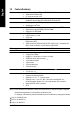
Question 10: Sometimes I hear different continuous beeps from computer after system boots up. What do these beeps usually stand for? Answer: The beep codes below may help you identify the possible computer problems. However, they are only for reference purposes. The situations might differ from case to case. g AWARD BIOS Beep Codes gAMI BIOS Beep Codes *Computer gives 1 short beep when system boots successfully. 1 short: System boots successfully *Except for beep code 8, these codes are always fatal.
English GA-8I915P Series Motherboard - 76 -
English - 77 - Appendix
English GA-8I915P Series Motherboard - 78 -
English Contact Us — Taiwan (Headquarters) — GIGA-BYTE TECHNOLOGY CO., LTD. NIPPON GIGA-BYTE CORPORATION Japan Address: No.6, Bau Chiang Road, Hsin-Tien, Taipei Hsien, Taiwan WEB address : http://www.gigabyte.co.jp — Singapore TEL: +886 (2) 8912-4888 GIGA-BYTE SINGAPORE PTE. LTD. FAX: +886 (2) 8912-4003 Tech. Support : Tech. Support : http://tw.giga-byte.com/TechSupport/ServiceCenter.htm http://tw.giga-byte.com/TechSupport/ServiceCenter.htm Non-Tech. Support(Sales/Marketing) : Non-Tech.
English — China — Australia NINGBO G.B.T. TECH. TRADING CO., LTD. Tech. Support : GIGABYTE TECHNOLOGY PTY. LTD. Address: 3/6 Garden Road, Clayton, VIC 3168 Australia http://cn.giga-byte.com/TechSupport/ServiceCenter.htm TEL: +61 3 85616288 Non-Tech. Support(Sales/Marketing) : FAX: +61 3 85616222 http://ggts.gigabyte.com.tw/nontech.asp WEB address : http://www.gigabyte.com.cn Tech. Support : http://www.giga-byte.com.au/TechSupport/ServiceCenter.htm Shanghai Non-Tech.