GA-8I915G-ZFD Intel® Pentium® 4 LGA775 Processor Motherboard User's Manual Rev.
Copyright © 2005 GIGA-BYTE TECHNOLOGY CO., LTD. All rights reserved. The trademarks mentioned in the manual are legally registered to their respective companies. Notice The written content provided with this product is the property of Gigabyte. No part of this manual may be reproduced, copied, translated, or transmitted in any form or by any means without Gigabyte's prior written permission. Specifications and features are subject to change without prior notice.
Table of Contents GA-8I915G-ZFD Motherboard Layout ........................................................................... 5 Block Diagram ............................................................................................................... 6 Chapter 1 Hardware Installation .................................................................................... 9 1-1 1-2 1-3 Considerations Prior to Installation ................................................................. 9 Feature Summary ..
Chapter 3 Install Drivers ............................................................................................ 43 3-1 Install Chipset Drivers ................................................................................... 43 3-2 3-3 Software Applications .................................................................................... 44 Driver CD Information ................................................................................... 44 3-4 3-5 Hardware Information ..............
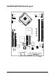
GA-8I915G-ZFD Motherboard Layout ATX_12V F_USB1 F_PANEL PWR_LED F_USB2 CPU_FAN F1_1394 PCI1 ATX DDR1 IDE ICH6 PCIE_16 RTL8110S S_ATA1 BAT SPDIF_IN S_ATA0 BIOS IT8712 CLR_CMOS SYS_FAN TSB43AB23 KB_MS 1394 LAN USB USB CD_IN LPT VGA -5- CODEC AZALIA_FP Intel 915G DDR2 GA-8I915G-ZFD LGA775 COMA AUDIO
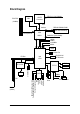
Block Diagram LGA775 Processor VGA PCI-ECLK (100MHz) CPUCLK+/-(200/133MHz) Host Interface PCI Express x16 Intel 915G GMCH DDR400/333MHz DIMM Dual Channel Memory GMCHCLK (200/133MHz) 66MHz 33MHz 14.
-7-
-8-
1-1 English Chapter 1 Hardware Installation Considerations Prior to Installation Preparing Your Computer The motherboard contains numerous delicate electronic circuits and components which can become damaged as a result of electrostatic discharge (ESD). Thus, prior to installation, please follow the instructions below: 1. Please turn off the computer and unplug its power cord. 2. When handling the motherboard, avoid touching any metal leads or connectors. 3.
English 1-2 Feature Summary CPU Chipset Memory Slots IDE Connections Onboard SATA Peripherals Onboard LAN Onboard Audio I/O Control Hardware Monitor BIOS Additional Features Overclocking Form Factor Supports the latest Intel ® Pentium ® 4 LGA775 CPU Supports 800/533MHz FSB L2 cache varies with CPU Northbridge: Intel ® 915G Express chipset Southbridge: Intel ® ICH6 2 DDR DIMM memory slots (supports up to 2GB memory) Sup
Installation of the CPU and Heatsink Before installing the CPU, please comply with the following conditions: 1. Please make sure that the motherboard supports the CPU. 2. Please take note of the one indented corner of the CPU. If you install the CPU in the wrong direction, the CPU will not insert properly. If this occurs, please change the insert direction of the CPU. 3. Please add an even layer of heat sink paste between the CPU and heatsink. 4.
English 1-4 Installation of Memory Before installing the memory modules, please comply with the following conditions: 1. Please make sure that the memory used is supported by the motherboard. It is recommended that memory of similar capacity, specifications and brand be used. 2. Before installing or removing memory modules, please make sure that the computer power is switched off to prevent hardware damage. 3. Memory modules have a foolproof insertion design.
1-5 Install expansion cards You can install your expansion card by following the steps outlined below: 1. Read the related expansion card's instruction document before install the expansion card into the computer. 2. Remove your computer's chassis cover, screws and slot bracket from the computer. 3. Press the expansion card firmly into expansion slot in motherboard. 4. Be sure the metal contacts on the card are indeed seated in the slot. 5.
English 1-6 I/O Back Panel Introduction PS/2 Keyboard and PS/2 Mouse Connector To install a PS/2 port keyboard and mouse, plug the mouse to the upper port (green) and the keyboard o the lower port (purple). IEEE 1394 port Connects to IEEE 1394 devices. USB port Before you connect your device(s) into USB connector(s), please make sure your device(s) such as USB keyboard, mouse, scanner, zip, speaker...etc. have a standard USB interface. Also make sure your OS supports USB controller.
English Side Speaker Out Connect the side surround speakers to this connector. You can use audio software to configure 2-/4-/5.1-/7.1-channel audio functioning.
English 1/2) ATX_12V/ATX (Power Connector) With the use of the power connector, the power supply can supply enough stable power to all the components on the motherboard. Before connecting the power connector, please make sure that all components and devices are properly installed. Align the power connector with its proper location on the motherboard and connect tightly. The ATX_12V power connector mainly supplies power to the CPU. If the ATX_12V power connector is not connected, the system will not start.
CPU_FAN / SYS_FAN (Cooler Fan Power Connector) The cooler fan power connector supplies a +12V power voltage via a 3-pin/4-pin (only for CPU_FAN) power connector and possesses a foolproof connection design. Most coolers are designed with color-coded power connector wires. A red power connector wire indicates a positive connection and requires a +12V power voltage. The black connector wire is the ground wire (GND). Please remember to connect the power to the cooler to prevent system overheating and failure.
English 6) S_ATA0/S_ATA1 (Serial ATA Connector, Controlled by ICH6) Serial ATA can provide up to 150MB/s transfer rate. Please refer to the BIOS setting for the Serial ATA and install the proper driver in order to work properly. Pin No. 1 7 Definition 1 2 GND TXP 3 4 TXN GND 5 6 RXN RXP 7 GND 7) F_PANEL (Front Panel Jumper) Please connect the power LED, PC peaker, reset switch and power switch etc of your chassis front panel to the F_PANEL connector according to the pin assignment below.
PWR_LED is connect with the system power indicator to indicate whether the system is on/off. It will blink when the system enters suspend mode. Pin No. 1 1 2 3 Definition MPD+ MPDMPD- 9) AZALIA_FP(Front Audio Panel Connector) This connector is supported to connect HD(High Definition) Audio and AC'97 Audio. Check the pin assignment carefully while you connect the audio panel cable, incorrect connection between the cable and connector will make the device unable to work or even damage it.
English 10) CD_IN (CD IN) Connect CD-ROM or DVD-ROM audio out to the connector. Pin No. 1 Definition 1 2 CD-L GND 3 4 GND CD -R 11) F_ USB1 / F_USB2 (Front USB Connector) Be careful with the polarity of the front USB connector. Check the pin assignment carefully while you connect the front USB cable, incorrect connection between the cable and connector will make the device unable to work or even damage it. For optional front USB cable, please contact your local dealer.
Serial interface standard set by Institute of Electrical and Electronics Engineers, which has features like high speed, high bandwidth and hot plug. Be careful with the polarity of the IEEE1394 connector. Check the pin assignment carefully while you connect the IEEE1394 cable, incorrect connection between the cable and connector will make the device unable to work or even damage it. For optional IEEE1394 cable, please contact your local dealer. Pin No.
English 14) CLR_CMOS (Clear CMOS) You may clear the CMOS data to its default values by this jumper. To clear CMOS, temporarily short 1-2 pin. Default doesn't include the "Shunter" to prevent from improper use this jumper. 1 Open: Normal 1 Short :Clear CMOS 15) BAT(Battery) Danger of explosion if battery is incorrectly replaced. Replace only with the same or equivalent type recommended by the manufacturer. Dispose of used batteries according to the manufacturer's instructions.
BIOS (Basic Input and Output System) includes a CMOS SETUP utility which allows user to configure required settings or to activate certain system features. The CMOS SETUP saves the configuration in the CMOS SRAM of the motherboard. When the power is turned off, the battery on the motherboard supplies the necessary power to the CMOS SRAM. When the power is turned on, pushing the button during the BIOS POST (Power-On Self Test) will take you to the CMOS SETUP screen.
English The BIOS Setup menus described in this chapter are for reference only and may differ from the exact settings for your motherboard. The Main Menu (For example: BIOS Ver. : FB) Once you enter Award BIOS CMOS Setup Utility, the Main Menu (as figure below) will appear on the screen. Use arrow keys to select among the items and press to accept or enter the sub-menu.
Optimized Defaults indicates the value of the system parameters which the system would be in best performance configuration. Set Supervisor Password Change, set, or disable password. It allows you to limit access to the system and Setup, or just to Setup. Set User Password Change, set, or disable password. It allows you to limit access to the system. Save & Exit Setup Save CMOS value settings to CMOS and exit setup. Exit Without Saving Abandon all CMOS value changes and exit setup.
English 2-1 Standard CMOS Features CMOS Setup Utility-Copyright (C) 1984-2005 Award Software Standard CMOS Features ` ` ` ` ` ` Date (mm:dd:yy) Time (hh:mm:ss) Fri, Apr 22 2005 16:55:24 Item Help Menu Level` IDE Channel 0 Master IDE Channel 0 Slave IDE Channel 2 Master IDE Channel 2 Slave IDE Channel 3 Master IDE Channel 3 Slave [None] [None] [None] [None] [None] [None] Change the day, month, year Halt On [All, But Keyboard] Base Memory Extended Memory Total Memory 640K 127M 128M Sun.
IDE HDD Auto-Detection Press "Enter" to select this option for automatic device detection. Extended IDE Drive SATA devices setup. You can use one of two methods: Auto Allows BIOS to automatically detect SATA IDE devices during POST. (Default value) None Select this if no SATA IDE devices are used and the system will skip the automatic detection step and allow for faster system start up. Access Mode Use this to set the access mode for the hard drive.
English 2-2 Advanced BIOS Features CMOS Setup Utility-Copyright (C) 1984-2005 Award Software Advanced BIOS Features ` Hard Disk Boot Priority First Boot Device Second Boot Device Third Boot Device Password Check # CPU Hyper-Threading Limit CPUID Max.
Setup System The system will boot but will not access to Setup page if the correct password is not entered at the prompt. (Default value) The system will not boot and will not access to Setup page if the correct password is not entered at the prompt. CPU Hyper-Threading Enabled Disabled Enables CPU Hyper Threading Feature. Please note that this feature is only working for operating system with multi processors mode supported. (Default value) Disables CPU Hyper Threading. Limit CPUID Max.
English 2-3 Integrated Peripherals CMOS Setup Utility-Copyright (C) 1984-2005 Award Software Integrated Peripherals On-Chip Primary PCI IDE On-Chip SATA Mode x PATA IDE Set to SATA Port 0/2 Set to SATA Port 1/3 Set to USB Controller USB 2.
Non-Combined Set On-Chip SATA mode to Enhanced, the motherboard allows up to 6 HDDs to use. Set On-Chip SATA mode to Non-Combined, SATA will be simulated to PATA mode. PATA IDE Set to Ch.1 Master/Slave Ch.0 Master/Slave Set PATA IDE to Ch. 1 Master/Slave. Set PATA IDE to Ch. 0 Master/Slave. (Default value) SATA Port 0/2 Set to This value will auto make by the setting "On-Chip SATA Mode" and "PATA IDE Set to". If PATA IDE were set to Ch. 1 Master/Slave,this function will auto set to Ch. 0 Master/Slave.
English Onboard LAN Boot ROM This function decide whether to invoke the boot ROM of the onboard LAN chip. Enabled Enable this function. Disabled Disable this function. (Default value) Onboard Serial Port 1 Auto 3F8/IRQ4 2F8/IRQ3 3E8/IRQ4 2E8/IRQ3 Disabled BIOS will automatically setup the port 1 address. Enable onboard Serial port 1 and address is 3F8/IRQ4. (Default value) Enable onboard Serial port 1 and address is 2F8/IRQ3. Enable onboard Serial port 1 and address is 3E8/IRQ4.
Power Management Setup English 2-4 CMOS Setup Utility-Copyright (C) 1984-2005 Award Software Power Management Setup ACPI Suspend Type Soft-Off by PWR-BTTN PME Event Wake Up Power On by Ring Resume by Alarm x Date (of Month) Alarm x Time (hh:mm:ss) Alarm Power On By Mouse Power On By Keyboard x KB Power ON Password AC Back Function [S1(POS)] [Instant-off] [Enabled] [Enabled] [Disabled] Everyday 0:0:0 [Disabled] [Disabled] Enter [Soft-Off] KLJI: Move Enter: Select F5: Previous Values +/-/PU/PD: Value F6
English Power On By Keyboard Password Disabled Keyboard 98 Enter from 1 to 5 characters to set the Keyboard Power On Password. Disabled this function. (Default value) If your keyboard have "POWER Key" button, you can press the key to power on the system. KB Power ON Password When "Power On by Keyboard" set at Password, you can set the password here. Enter Input password (from 1 to 5 characters) and press Enter to set the Keyboard Power On password.
PnP/PCI Configurations CMOS Setup Utility-Copyright (C) 1984-2005 Award Software PnP/PCI Configurations PCI 1 IRQ Assignment PCI 2 IRQ Assignment KLJI: Move Enter: Select F5: Previous Values [Auto] [Auto] +/-/PU/PD: Value F6: Fail-Safe Defaults Item Help Menu Level` F10: Save ESC: Exit F1: General Help F7: Optimized Defaults PCI 1 IRQ Assignment Auto 3,4,5,7,9,10,11,12,14,15 Auto assign IRQ to PCI 1. (Default value) Set IRQ 3,4,5,7,9,10,11,12,14,15 to PCI 1.
English 2-6 PC Health Status CMOS Setup Utility-Copyright (C) 1984-2005 Award Software PC Health Status Vcore DDR25V +3.
MB Intelligent Tweaker(M.I.T.) CMOS Setup Utility-Copyright (C) 1984-2005 Award Software MB Intelligent Tweaker(M.I.T.) CPU Clock Ratio C.I.A.
English CPU Host Clock Control Please note that if your system is overclocked and cannot restart, please wait 20secs. for automatic system restart or clear the CMOS setup data and perform a safe restart. Disabled Disable CPU Host Clock Control. (Default value) Enabled Enable CPU Host Clock Control. CPU Host Frequency (Mhz) 100MHz ~ 600MHz Set CPU Host Frequency from 100MHz to 600MHz. If you use FSB533 Pentium 4 processor, please set "CPU Host Frequency" to 133MHz.
Load Fail-Safe Defaults English 2-8 CMOS Setup Utility-Copyright (C) 1984-2005 Award Software ` ` ` ` ` ` ` Standard CMOS Features Load Fail-Safe Defaults Advanced BIOS Features Load Optimized Defaults Integrated Peripherals Set Supervisor Password Power Management Setup Set User Password Load Fail-Safe DefaultsSave (Y/N)? N Setup PnP/PCI Configurations & Exit PC Health Status Exit Without Saving MB Intelligent Tweaker(M.I.T.
English 2-10 Set Supervisor/User Password CMOS Setup Utility-Copyright (C) 1984-2005 Award Software ` ` ` ` ` ` ` Standard CMOS Features Advanced BIOS Features Integrated Peripherals Power Management Setup PnP/PCI Configurations Enter Password: PC Health Status MB Intelligent Tweaker(M.I.T.
English 2-11 Save & Exit Setup CMOS Setup Utility-Copyright (C) 1984-2005 Award Software ` ` ` ` ` ` ` Standard CMOS Features Load Fail-Safe Defaults Advanced BIOS Features Load Optimized Defaults Integrated Peripherals Set Supervisor Password Power Management Setup Set User Password PnP/PCI Configurations Save & Exit Setup Save to CMOS and EXITExit (Y/N)? Y Saving PC Health Status Without MB Intelligent Tweaker(M.I.T.
English GA-8I915G-ZFD Motherboard - 42 -
Pictures below are shown in Windows XP. Insert the driver CD-title that came with your motherboard into your CD-ROM drive, the driver CD-title will auto start and show the installation guide. If not, please double click the CD-ROM device icon in "My computer", and execute the Run.exe. 3-1 Install Chipset Drivers After insert the driver CD, "Xpress Install" will scan automatically the system and then list all the drivers that recommended to install.
English 3-2 Software Applications This page displays all the tools that Gigabyte developed and some free software, you can choose anyone you want and press "install" to install them. 3-3 Driver CD Information This page lists the contents of software and drivers in this CD-title.
Hardware Information English 3-4 This page lists all device you have for this motherboard. 3-5 Contact Us Please see the last page for details.
English GA-8I915G-ZFD Motherboard - 46 -
4-1 English Chapter 4 Appendix Unique Software Utilities (Not all model support these Unique Software Utilities, please check your MB features.) U-PLUS D.P.S. (Universal Plus Dual Power System) The U-Plus Dual Power System (U-Plus DPS) is a revolutionary eight-phase power circuit built for ultimate system protection. Designed to withstand varying current levels and changes, the U-Plus D.P.S. provides an immensely durable and stable power circuit to the CPU for solid system stability.
English 4-1-1 Xpress Recovery Introduction What is Xpress Recovery ? Xpress Recovery is a utility used to back up and restore an OS partition. If the hard drive is not working properly, the user can restore the drive to its original state. 1. 2. 3. 4. 5. 6. Supports FAT16, FAT32, and NTFS formats Must be connected to the IDE1 Master Allows installation of only one OS Must be used with an IDE hard disk supporting HPA The first partition must be set as the boot partition.
Press F9 during powering on the computer. (Text Mode) English 2. Award Modular BIOS v6.00PG, An Energy Star Al ly Copyright (C) 1984-2004, Award Software, Inc. Intel 865PE AGPSet BIOS for 8IPE1000MT F1 Check System Health OK . . . F9 For Xpress Recovery Press DEL to enter SETUP / Q-Flash, F9 For Xpress Recovery 08/16/2002-I845GE-6A69YG01C-00 Xpress Recovery V1.0 (C) Copy Right 2003. GIGABYTE Technology CO. , Ltd. 1. Execute Backup Utility 2. Execute Restore Utility 3. Remove Backup Image 4.
English 1. Execute Backup Utility: Press B to Backup your System or Esc to Exit The backup utility will automatically scan your system and back up data as a backup image in your hard drive. Not all systems support access to Xpress Recovery by pressing the F9 key during computer power on. If this is the case, please use the boot from CD-ROM method to enter Xpress Recovery. 2. Execute Restore Utility: This program will recover your system to factory default.
Method 1 : Q-FlashTM Utility Q-FlashTM is a BIOS flash utility embedded in Flash ROM. With this utility, users only have to stay in the BIOS menu when they want to update BIOS. Q-Flash?allows users to flash BIOS without any utility in DOS or Windows. Using Q-FlashTM indicating no more fooling around with any complicated instructions and operating system since it is in the BIOS menu.
English Entering the Q-FlashTM utility: Step1: To use Q-Flash utility, you must press Del in the boot screen to enter BIOS menu. CMOS Setup Utility-Copyright (C) 1984-2004 Award Software Standard CMOS Features Advanced BIOS Features Integrated Peripherals Power Management Setup PnP/PCI Configurations PC Health Status MB Intelligent Tweaker(M.I.T.
This section tells you how to update BIOS using the Q-Flash utility. As described in the "Before you begin" section above, you must prepare a floppy disk having the BIOS file for your motherboard and insert it to your computer. If you have already put the floppy disk into your system and have entered the Q-Flash utility, please follow the steps below to flash BIOS. Steps: 1.
English 3. Press Y button on your keyboard after you are sure to update BIOS. Then it will begin to update BIOS. The progress of updating BIOS will be displayed. Please do not take out the floppy disk when it begins flashing BIOS. 4. Press any keys to return to the Q-Flash menu when the BIOS updating procedure is completed. Dual BIOS Utility Boot From......................................... Main Bios Main ROM Type/Size.............................SST 49LF004A Backup ROM Type/Size.........................
Press Del to enter BIOS menu after system reboots. When you are in BIOS menu, move to Load Fail-Safe Defaults item and press Enter to load BIOS Fail-Safe Defaults. Normally the system redetects all devices after BIOS has been upgraded. Therefore, we highly recommend reloading the BIOS defaults after BIOS has been upgraded.
English Exploring the Q-FlashTM utility screen The Q-FlashBIOS utility screen consists of the following key components. Q-FlashTM utility bar Q-Flash Utility V1.30 Flash Type/Size.................................SST 49LF003A Task menu for Q-FlashTM utility Enter : Run Keep DMI Data Enable Update BIOS from Floppy Save BIOS to Floppy :Move ESC:Reset 256K F10:Power Off Action bar Task menu for Q-Flash utility: Contains the names of three tasks.
Press Y button on your keyboard after you are sure to update BIOS. Then it will begin to update BIOS. The progress of updating BIOS will be shown at the same time. Q-Flash Utility V1.30 Flash Type/Size.................................SST 49LF002A 256K Keep DMI Data BIOS Enable Updating Now Update BIOS from Floppy >>>>>>>>>>>>>>>>>>>......................... Save BIOS to Floppy EnterDon't : Run :Moveor ResetESC:Reset F10:Power Off Turn Off Power System 4.
English Method 2 : @BIOSTM Utility If you do not have a DOS startup disk, we recommend that you use the new @BIOS utility. @BIOS allows users to update their BIOS under Windows. Just select the desired @BIOS server to download the latest version of BIOS. Fig 1. Installing the @BIOS utility Fig 2. Installation Complete and Run @BIOS Click Sart/ Programs/ GIGABYTE/@BIOS Select @BIOS item than click Install Fig 3. The @BIOS Utility Click " " Fig 4.
IV. Check out supported motherboard and Flash ROM: In the very beginning, there is "About this program" icon shown in dialog box. It can help you check out which kind of motherboard and which brand of Flash ROM are supported. 2. Note: I. In method I, if it shows two or more motherboard's model names to be selected, please make sure your motherboard's model name again. Selecting wrong model name will cause the system unbooted. II.
English 4-1-3 2 / 4 / 5.1 / 7.1 Channel Audio Function Introduction After installation of the audio driver, you'll find an icon in the system area. Double click the icon to select the function. If the icon can not be found, go to the control panel from the system menu and double click the C-Media CPL icon. Open "CMI Audio Config" and then go to "Information" tab. Make sure "Show the audio configuration icon in the system tray" is checked.
We recommend that you use speakers with amplifier to acquire the best sound effect if the stereo output is applied. STEP 1: Connect the stereo speakers or earphone to "Line Out". Line Out STEP 2: After installation of the audio driver, you'll find an icon in the system area. Double click the icon to select the function. STEP 3: Click "C-Media 3D Audio Configuration" and then select "Main Setting". The current audio mode is displayed in "Audio System Status".
English 4 Channel Audio Setup STEP 1 : Connect the front speaker to "Front Speaker Out" and the surround speaker to "Surround speaker out". Front Speaker Out Surround speaker out STEP 2: After installation of the audio driver, you'll find an icon in the system area. Double click the icon to select the function. STEP 3: Click "C-Media 3D Audio Configuration" and then select "Main Setting". The current audio mode is display in "Audio System Status".
STEP 1 : Connect the front speaker to "Front Speaker Out", the surround speaker to "Surround speaker out", and the center/subwoofer speaker to "Center/Subwoofer Speaker Out". Front Speaker Out Center/Subwoofer Speaker Out Surround speaker out STEP 2: After installation of the audio driver, you find an icon in the system area. Double click the icon to select the function. STEP 3: Click "C-Media 3D Audio Configuration" and then select "Main Setting".
English 7.1 Channel Audio Setup STEP 1 : Connect the front speaker to "Front Speaker Out", the surround speaker to "Surround speaker out", and the center/subwoofer speaker to "Center/Subwoofer Speaker Out", and the back surround speaker to "Back surround speaker out". Front Speaker Out Back surround speaker out Center/Subwoofer Speaker Out Surround speaker out STEP 2: After installation of the audio driver, you find an icon in the system area. Double click the icon to select the function.
English Digital I/O Status: Digital Output Status-(1) For stereo PCM output: sampling rate is shown here. (2) For Dolby Digital Live! output: AC3 is shown here. Digital Input Status-(1) For stereo PCM input: sampling rate is shown here. Mixer The build-in mixer allows users to control volume and monitor sound recording.
English 4-2 Troubleshooting Below is a collection of general asked questions. To check general asked questions based on a specific motherboard model, please log on to http://www.gigabyte.com.tw Question 1: I cannot see some options that were included in previous BIOS after updating BIOS. Why? Answer: Some advanced options are hidden in new BIOS version. Please press Ctrl and F1 keys after entering BIOS menu and you will be able to see these options.
English - 67 - Appendix
English GA-8I915G-ZFD Motherboard - 68 -
English - 69 - Appendix
English GA-8I915G-ZFD Motherboard - 70 -
English Contact Us Taiwan (Headquarters) GIGA-BYTE TECHNOLOGY CO., LTD. Japan NIPPON GIGA-BYTE CORPORATION Address: No.6, Bau Chiang Road, Hsin-Tien, Taipei 231, Taiwan WEB address : http://www.gigabyte.co.jp Singapore TEL: +886-2-8912-4888 FAX: +886-2-8912-4003 GIGA-BYTE SINGAPORE PTE. LTD. Tech. Support : Tech. Support : http://tw.giga-byte.com/TechSupport/ServiceCenter.htm http://tw.giga-byte.com/TechSupport/ServiceCenter.htm Non-Tech. Support(Sales/Marketing) : Non-Tech.
English China Russia NINGBO G.B.T. TECH. TRADING CO., LTD. Tech. Support : Moscow Representative Office Of GIGA-BYTE Technology Co., Ltd. http://tw.giga-byte.com/TechSupport/ServiceCenter.htm Non-Tech. Support(Sales/Marketing) : Tech. Support : http://tw.giga-byte.com/TechSupport/ServiceCenter.htm http://ggts.gigabyte.com.tw/nontech.asp WEB address : http://www.gigabyte.com.cn Non-Tech. Support(Sales/Marketing) : http://ggts.gigabyte.com.tw/nontech.