GA-4MXSV Pentium Prescott 1066 Motherboard USER’S MANUAL Pentium®Prescott Processor Motherboard Rev.
English GA-4MXSV Motherboard Table of Content Item Checklist ........................................................................................ 4 WARNING! ............................................................................................... 4 Chapter 1 Introduction ............................................................................ 5 Features Summary ...................................................................................... 5 GA-4MXSV Motherboard Layout ...............
Chapter 4 Technical Reference ............................................................ 61 Block Diagram ........................................................................................... 61 Chapter 5 Driver Installation .................................................................. 62 A.Intel Chipset Software Installation Utilities .................................................................. 62 B.Intel LAN Driver Installation ..........................................................
English GA-4MXSV Motherboard Item Checklist The GA-4MXSV motherboard IDE (ATA100 ) cable x 1 / Floppy cable x 1 Serial ATA cable x 4 I/O Shield Kit CD for motherboard driver & utility GA-4MXSV user’s manual WARNING! Computer motherboards and expansion cards contain very delicate Integrated Circuit (IC) chips. To protect them against damage from static electricity, you should follow some precautions whenever you work on your computer. 1. Unplug your computer when working on the inside. 2.
Introduction Chapter 1 Introduction Features Summary Form Factor CPU 12” x 9.6” ATX size form factor, 6 layers PCB.
English GA-4MXSV Motherboard On-Board Graphic ATI ES1000 with 16Mb DDR SDRAM On-Board LAN Dual Intel 82573V Gigabit Ethernet controllers Hardware Monitor Winbond 83792D controller Enhanced features with CPU Vcore, 1.5V reference, VCC3 (3.3V), VCC5V, +12V, 2.
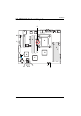
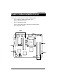
Introduction GA-4MXSV Motherboard Layout 5 M U O O P V W X Y L 6 A Q S J T 7 K 2 R E 4 3 B D 1 C Z N F H G 8 I 7 9
English GA-4MXSV Motherboard A. CPU U. PCI_B B. Intel Mukilteo V PCI_A C. D. Intel 6702 PXH-V Intel ICH7R W. X. PCI-E x8 PCI-X_2 E. F. ITE IT8712F SATA1 Y. Z. PCI-X_1 BAT (Battery) G. H. SATA2 SATA3 1. 2. ATX ATX12V I. J. SATA4 FDC 3. 4. WOR WOL K. L. IDE F_Panel 5. 6. UF1 (CPU FAN) UF2 (System FAN) M. N. COM2 USB2 7. 8. UF3 (System FAN) UF4 (System FAN) O. Intel 82573V GbE 9. UF5 (System FAN) P. Q. ATI RN50 DDRII A1 R. S. DDRII A2 DDRII B1 T.
Connector Introduction Chapter 2 Hardware Installation Process To set up your computer, you must complete the following steps: Step 1- Install the Central Processing Unit (CPU) Step 2- Install memory modules Step 3- Install expansion cards Step 4- Connect ribbon cables, cabinet wires, and power supply Step 5- Setup BIOS software Step3 Step1 Step4 Step 4 Step 4 Step4 Step 2 9
English GA-4MXSV Motherboard Step 1: Installing Processor and CPU Haet Sink Before installing the processor and cooling fan, adhere to the following cautions: 1. The processor will overheat without the heatsink and/or fan, resulting in permanent irreparable damage. 2. Never force the processor into the socket. 3. Apply thermal grease on the processor before placing cooling fan. 4. Please make sure the CPU type is supported by the motherboard. 5.
Hardware Installation Process Step1-2: Installing Heat Sink Male Push Pin The top of Female Push Pin Female Push Pin Fig.1 Please apply heatsink paste on the surface of the installed CPU. Fig. 2 ( to remove the heatsink, turning the push pin along the direction of arrow; and reverse the previous step to install the heat sink.) Please note the direction of arrow sign on the male push pin doesn't face inwards before installation. (This instruction is only for Intel boxed fan) Fig.
English GA-4MXSV Motherboard Step 2: Install memory modules Before installing the processor and heatsink, adhere to the following warning: When DIMM LED is ON, do not install/remove DIMM from socket. GA-4MXSV has 4 dual inline memory module (DIMM) socets. It supports the Dual Channel Technology. The BIOS will automatically detects memory type and size during system boot. For detail DIMM installation, please refer to the following instructions.
Hardware Installation Process Table 1. Supported DIMM Module Type Technology 256MB 512MB 1GB Organization 8MB x 8 x 4 bks 16MB x 4 x 4bks 16MB x 8 x 4bks 32MB x 4 x 4bks 32MB x 8 x 4bks 64MB x 4 x 4bks SDRAM Chips/DIMM 8 16 8 16 8 16 Table 2. DIMM Placement DDR2-533/667 DIMM Configuration DIMM1 DIMM2 1 1 2 1 2 Empty Empty Empty Empty Empty Empty Empty Single Rank Single Rank Dual Rank Single Rank Dual Rank Single Rank Dual Rank, 1 Single Rank Dual Rank Installation Steps: 1.
English GA-4MXSV Motherboard Step 3: Install expansion cards 1. Read the related expansion card’s instruction document before install the expansion card into the computer. 2. Remove your server’s chassis cover, necessary screws and slot bracket from the computer. 3. Press the expansion card firmly into expansion slot in motherboard. 4. Be sure the metal contacts on the card are indeed seated in the slot. 5. Replace the screw to secure the slot bracket of the expansion card. 6.
Hardware Installation Process Step 4: Connect ribbon cables, cabinet wires, and power supply Step 4-1 : I/O Back Panel Introduction 15
English GA-4MXSV Motherboard PS/2 Keyboard and PS/2 Mouse Connector To install a PS/2 port keyboard and mouse, plug the mouse to the upper port (green) and the keyboard to the lower port (purple). USB Port Before you connect your device(s) into USB connector(s), please make sure your device(s) such as USB keyboard, mouse, scanner, zip, speaker...etc. have a standard USB interface. Also make sure your OS supports USB controller.
Connector Introduction Step 4-2 :Connectors & Jumper Setting Introduction N F E O D B P L M S T C Q V GH J I R K U A) B) C) D) E) F) G) H) I) J) K) L) ATX ATX _12V IDE1 FDC1 F_Panel COM2 USB2 S_ATA1 S_ATA2 S_ATA3 S_ATA4 WOL1 M) N) O) P) Q) R) S) T) U) V) 17 WOR1 UF1 (CPU Fan) UF2 (System Fan) UF3 (System Fan) UF4 (System Fan) UF5 (System Fan) CLR_CMOS RECOVERY PASSWORD BAT (Battery) A
English GA-4MXSV Motherboard A) ATX (ATX Power Connector) AC power cord should only be connected to your power supply unit after ATX power cable and other related devices are firmly connected to the mainboard. PIN No. Definition 1 2 +3.3V +3.3V 3 4 GND +5V 5 6 GND +5V 7 8 GND POK 9 10 5VSB +12V 11 12 +12V +3.3V 13 14 +3.3V -12V 15 16 GND PSON 17 18 GND GND 19 20 GND -5V 21 22 +5V +5V 23 24 +5V GND 13 24 B ) ATX_12V( +12V Power Connector) 8 1 5 4 Pin No.
Connector Introduction C ) IDE1 (IDE Connector) Please connect first harddisk to IDE1. The red stripe of the ribbon cable must be the same side with the Pin1. 1 39 2 40 D) FDC1 (Floppy Connector) Please connect the floppy drive ribbon cables to FDD. It supports 720K,1.2M,1.44M and 2.88Mbytes floppy disk types. The red stripe of the ribbon cable must be the same side with the Pin1.
English GA-4MXSV Motherboard E ) F_Panel1 (2X9 Pins Front Panel connector) Please connect the power LED, PC speaker, reset switch and power switch of your chassis front panel to the F_PANEL connector according to the pin assignment above.
Connector Introduction F ) COM2 1 2 9 10 Pin No. 1 2 3 4 5 6 7 8 9 10 Definition DCDSIN2 SOUT2 DTR2GND DSR2RTS2CTS2RI2NC G ) USB2 (Front USB Connector) Be careful with the polarity of the front panel USB connector. Check the pin assignment while you connect the front panel USB cable. Please contact your nearest dealer for optional front panel USB cable. 1 2 9 10 21 Pin No.
English GA-4MXSV Motherboard H / I / J / K ) S_ATA1/ 2/ 3/ 4 (Serial ATA Connectors) You can connect the Serial ATA device to this connector, it provides you high speed transfer rates (150MB/sec). 1 Pin No. 1 2 3 4 5 6 7 7 S_ATA1 Definition GND TXP TXN GND RXN RXP GND S_ATA3 S_ATA4 S_ATA2 L ) WOL1 (Wake on LAN) This connector allows the remove servers to manage the system that installed this mainboard via your network adapter which also supports WOL. Pin No.
Connector Introduction M ) WOR1 (Wake on Ring) Pin No. 1 2 Definition MODEM RING ON GND 1 N ) UF1 (CPU Fan Connector) Please note, a proper installation of the CPU cooler is essential to prevent the CPU from running under abnormal condition or damaged by overheating.The CPU fan connector supports Max. current up to 1A . 1 23 Pin No.
English GA-4MXSV Motherboard O / P / Q / R ) UF2/3/4/5 (System Fan Connectors) This connector allows you to link with the cooling fan on the system case to lower the system temperature. These connectors are for system use only. UF2 1 Pin No. 1 2 3 4 UF3 1 Definition GND 12V Sense Control UF4 UF5 S ) CLR_CMOS (Clear CMOS Function) You may clear the CMOS data to its default values by this jumper. Default value doesn’t include the “Shunter” to prevent from improper use this jumper.
Connector Introduction T ) RECOVERY ( BIOS Recovery Function) 1 1-2 close: Enable BIOS Recovery function. 1 2-3 close: Disable this function. (Default value) Please remove the jumper when system access recovery flopp disk. U ) PASSWORD (Clear CMOS Password Function) Open: Clear Password Short: Normal (Default) Please remove the jumper when system reboot next time.
English GA-4MXSV Motherboard V ) BAT1 (Battery) CAUTION Danger of explosion if battery is incorrectly replaced. Replace only with the same or equivalent type recommended by the manufacturer. Dispose of used batteries according to the manufacturer’s instructions. If you want to erase CMOS... 1.Turn OFF the computer and unplug the power cord. 2.Remove the battery, wait for 30 second. 3.Re-install the battery. 4.Plug the power cord and turn ON the computer.
BIOS Setup Chapter 3 BIOS Setup BIOS Setup is an overview of the BIOS Setup Program. The program that allows users to modify the basic system configuration. This type of information is stored in battery-backed CMOS RAM so that it retains the Setup information when the power is turned off. ENTERINGSETUP Power ON the computer and press immediately will allow you to enter Setup.
GA-4MXSV Motherboard GETTINGHELP Main Menu The on-line description of the highlighted setup function is displayed at the bottom of the screen. Status Page Setup Menu / Option Page Setup Menu Press F1 to pop up a small help window that describes the appropriate keys to use and the possible selections for the highlighted item. To exit the Help Window press . z Main This setup page includes all the items in standard compatible BIOS.
BIOS Setup Main Once you enter Phoenix BIOS Setup Utility, the Main Menu (Figure 1) will appear on the screen. Use arrow keys to select among the items and press to accept or enter the sub-menu. Figure 1: Main System Time The time is calculated based on the 24-hour military time clock. Set the System Time (HH:MM:SS) System Date Set the System Date. Note that the “Day” automatically changed after you set the date.
GA-4MXSV Motherboard Legacy Diskette A/B This category identifies the type of floppy disk drive A that has been installed in the computer. Disabled Disable this device. 360KB, 5 in. 31/2 inch AT-type high-density drive; 360K byte capacity 1.2MB, 31/2 in. 31/2 inch AT-type high-density drive; 1.2M byte capacity 720K, 31/2 in. 31/2 inch double-sided drive; 720K byte capacity 1.44M, 3 1/2 in. 31/2 inch double-sided drive; 1.44M byte capacity. 2.88M, 3 31/2 inch double-sided drive; 2.
BIOS Setup TYPE 1-39: Predefined types. Users: Set parameters by User. Auto: Set parameters automatically. (Default Vaules) CD-ROM: Use for ATAPI CD-ROM drives or double click [Auto] to set all HDD parameters automatically. ATAPI Removable: Removable disk drive is installed here. Multi-Sector Transfer This field displays the information of Multi-Sector Transfer Mode. Disabled: The data transfer from and to the device occurs one sector at a time.
GA-4MXSV Motherboard Advanced Processor Options Figure 1-1: Advanced Processor Option Advanced Processor Option This category includes the information of CPU Speed, Processor ID, Processor L2 Cache. And setup menu for C1 Enhanced Mode, No Execute Mode Memory Protection, and Processor Power Management. Processor Reset Yes Select ‘Yes’ BIOS will clear historical processor status and reset all processors on next boot. No Disables Processor Reset function.
BIOS Setup C1 Enhanced Mode With enabling C1 Enhanced Mode, all loical processors in the physical processor have entered the C1 state, the processor will reduce the core clock frequency to system bus ratio and VID. Enabled Enabled C1 Enhanced Mode. Disabled Disables C1 Enhanced Mode. (Default value) No Execute Mode Mem. Protection Enabled Enable No Execute Mode Memory Protection function. (Default value) Disabled Disables No Execute Mode Memory Protection function.
GA-4MXSV Motherboard Advanced About This Section: Advanced With this section, allowing user to configure your system for basic operation. User can change the processor options, chipset configuration, PCI configuration and chipset control.
BIOS Setup Memory Configuration Figure 2-1: Memory Configuration Installed Memory/Available to OS/DIMM Group 1,2,3,4 Status These category is display-only which is determined by POST (Power On Self Test) of the BIOS. Memory Reset Yes Select ‘Yes’, system will clear the memory error status. Save the changes and restart system. After rebooting system, the Memory Reset item will set to ‘No’ automatically. No Disable this function.
GA-4MXSV Motherboard PCI Configuration Figure 2-2: PCI Configuration Embedded NIC #1 Onboard LAN1 Control Enabled Enable onboard LAN1 device. (Default value) Disabled Disable this function. Option ROM Scan Enabled Enableing this item to initialize device expansion ROM. Disabled Disable this function.
BIOS Setup PCI Slot 1/2/3/4/5 Option ROM Enabled Enableing this item to initialize device expansion ROM. (Defualt value) Disabled Disable this function.
GA-4MXSV Motherboard I/O Device Configuration Figure 2-3: I/O Device Configuration 38
BIOS Setup Serial Port A This allows users to configure serial prot A by using this option. Enabled Enable the configuration (Default value) Disabled Disable the configuration. Base I/O Address/IRQ 3F8 Set IO address to 3F8. (Default value) 2F8 Set IO address to 2F8. 3E8 Set IO address to 3E8. 2E8 Set IO address to 2E8. IRQ IRQ3 Set Interrupt as IRQ3. IRQ4 Set Interrupt as IRQ4.(Default value) Serial Port B This allows users to configure serial prot B by using this option.
GA-4MXSV Motherboard Parallel Port This allows users to configure parallel port by using this option. Enabled Enable the configuration. Disabled Disable the configuration. (Default value) Mode This option allows user to set Parallel Port transfer mode. Bi-directional Use this setting to support bi-directional transfers on the parallel port. (Default value) EPP Using Parallel port as Enhanced Parallel Port. ECP Using Parallel port as Extended Capabilities Port.
BIOS Setup USB 2.0 Controller This item allows users to enable or disable the USB 2.0 device by setting item to the desired value. Enabled Enable USB 2.0 controller. (Default value) Options Disbale this function. Legacy USB Support This option allows user to function support for legacy USB. Enabled Enables support for legacy USB (Default Value) Disabled Disables support for legacy USB Route Port 80h cycles to Set route port 80h cycles to either PCI or LPC bus.
GA-4MXSV Motherboard Serial ATA Enabled Enables on-board serial ATA function. (Default Value) Disabled Disables on-board serial ATA function. ` Native Mode Operation This option allows user to set the native mode for Serial ATA function. Auto Auto detected. (Default value) Serial ATA Set Native mode to Serial ATA. ` SATA Controller Mode Option Compatible Mode SATA and PATA drives are auto-detected and placed in Enhanced Mode SATA and PATA drives are auto-detected and placed in Native mode.
BIOS Setup Advanced Chipset Control Figure 2-4: Advanced Chipset Control Enable Multimedia Timer Enabled Enable Multimedia Timer support. Disabled Disable this function. (Default value) PCI Express Sub-Menu These items are for debugging the PCI-Express Ports. PCI Device ` PCI IRQ Line 1/2/3/4/5 When ACPI device cannot use IRQs already in use by ISA or EISA devices. Use ‘Auto Select’ only if no ISA or EISA legacy cards are installed. Auto Select Auto selecting PCI IRQ lines.
GA-4MXSV Motherboard Wake On LAN / PME This option allow user to determine the action of the system when a LAN/PME wake up event occurs. Enabled Enable Wake On LAN/PME. (Default value) Disabled Disable this function. Note: This item must enabled if you’re running under Windows operating system. Wake On Ring This option allow user to determine the action of the system power is off and the modem is ringing. Enabled Enable Wake On Ring. (Default value) Disabled Disable this function.
BIOS Setup Hardware Monitor Figure 2-5: Hardware Monitor CPU / Motherboard/ Ambit Temperature Display the current CPU temperature, Motherboard, and Ambient temperature. Voltage Monitor: 3V Dual, VCC3, VCC, 12V2, 12V1, VBAT, 5VSB Detect system's voltage status automatically. FAN Monitor: System 1/2/3/4/5/6/7/8 (RPM) Display the current System FAN 1/2/3/3/4/5/6/7/8 speed. This Menu will disappear when BMC module is populated.
GA-4MXSV Motherboard Boot -time Diagnostic When this item is enabled, system will shows Diagnostic status when system boot. Enabled Enable Boot-time Diagnostic. Disabled Disable this function. (Default value) Reset Configuration Data Yes Reset all configuration data. No Do not make any changes. (Default value) NumLock This option allows user to select power-on state for NumLock. On Enable NumLock. Off Disable this function.
BIOS Setup Security * About This Section: Security In this section, user can set either supervisor or user passwords, or both for different level of password securities. In addition, user also can set the virus protection for boot sector. Figure 3: Security Set User Password You can only enter but do not have the right to change the options of the setup menus. When you select this function, the following message will appear at the center of the screen to assist you in creating a password.
GA-4MXSV Motherboard Set Supervisor Password You can install and change this options for the setup menus. Type the password up to 6 characters in lengh and press . The password typed now will clear any previously entered password from the CMOS memory. You will be asked to confirm the entered password. Type the password again and press . You may also press to abort the selection and not enter a specified password or press key to disable this option.
BIOS Setup Server Figure 4: Server 49
GA-4MXSV Motherboard System Management Figure 4-1: System Management Server Management This category allows user to view the server management features. Including information of BIOS Version. All items in this menu cannot be modified in user’s mode. If any items require changes, please consult your system supervisor.
BIOS Setup Console Redirection Figure 4-2: Console Redirection BIOS Redirection Port If this option is set to enabled, it will use a port on the motherboard. On-board COMA Use COMA as he COM port address. Disabled Disable this function. (Default value) Note: Tower has COMA and COMB. Baud Rate This option allows user to set the specified baud rate. Options 300, 1200, 2400, 9600, 19.2K, 38.4K, 57.6K, 115.2K. Terminal Type This option allows user to select the specified terminal type.
GA-4MXSV Motherboard Flow Control This option provide user to enable the flow control function. None Not supported. XON/OFF Software control. CTS/RTS Hardware control. (Default value) Console Connect This field indicates whether the console is connected directly to the system or a modem is used to connect. Direct Console is connected directly to the system. (Default) Disabled Console is connected via the modem. Continue C.R.
BIOS Setup Post Error Pause If this item is set to enabled, the system will wai for user intervention on critical POST errors. If this item is disabled, the system will boot with no intervention if possible. Enabled Enable Post Error Pause. (Default value) Disabled Disable this function. AC-LINK This option provides user to set the mode of operation if an AC / power loss occurs. Power On System power state when AC cord is re-plugged. Stay Off Do not power on system when AC power is back.
GA-4MXSV Motherboard Event Log Viewer Enabled Enable Event Log Viewer function(Default value) Disabled Disable this function. This option will disappear and disable when BMC module is populated.
BIOS Setup Set Threshold Figure 4-4: Set Threshold System Fan 1/2/3/4/5/6 Error Enabled Enable System Fan 1/2/3/4/5/6 Fan Error. (Default value) Disabled Disable this function. M/B Voltage Error Enabled Motherboard Voltage Error. (Default value) Disabled Disable this function. M/B Temperature Error Enabled Motherboard Temperature Error. (Default value) Disabled Disable this function.
GA-4MXSV Motherboard Boot * About This Section: Boot The “Boot” menu allows user to select among four possible types of boot devices listed using the up and down arrow keys. By applying <+> and key, you can promote devices and by using the <-> key, you can demote devices. Promotion or demotion of devices alerts the priority that the system uses to search for boot device on system power on.
BIOS Setup Exit Figure 6: Exit * About This Section: Exit Once you have changed all of the set values in the BIOS setup, you should save your chnages and exit BIOS setup program. Select “Exit” from the menu bar, to display the following sub-menu.
GA-4MXSV Motherboard Exit Saving Changes This option allows user to exit system setup with saving the changes. Press on this item to ask for the following confirmation message: Pressing ‘Y’ to store all the present setting values tha user made in this time into CMOS. Therefore, whenyou boot up your computer next time, the BIOS will re-configure your system according data in CMOS.
BIOS Setup Load Settup Default This option allows user to load default values for all setup items. When you press on this item, you will get a confirmation dialog box with a message as below: Discard Changes This option allows user to load previos values from CMOS for all setup item.
GA-4MXSV Motherboard Save Changes This option allows user to save setup dat ato CMOS. When you press on this item, you will get a confirmation dialog box with a message as below: Press [Yes] to save setup daya to CMOS.
VGA Connector x2 Front Side USB 2.0 ATI RN50 BUS Switch PCI 32/33MHz PCI 32/33MHz PXH-V PCI-E to PCI-X Bridge PCI-X 100MHz PCI-X 100MHz PCIE x 8 PCI PCI-E x4 PCI-E x8 FWH COM1 KB&MS VRD 10.
GA-4MXSV Motherboard Revision Chapter History 5 Driver Installation A. Intel Chipset Software Installation Utilities Insert the driver CD-title that came with your motherboard into your CD-ROM driver, the driver CD-title will auto start and show a series of Setup Wizard dialog boxes. If not, please double click the CD-ROM device icon in "My computer", and execute the setup.exe. Installation Procedures: 1.
Driver Installation Installation Completed 5. Installation completed, Click "Finish" to restart computer.
GA-4MXSV Motherboard B. Intel LAN Driver Installation Insert the driver CD-title that came with your motherboard into your CD-ROM driver, the driver CD-title will auto start and show a series of Setup Wizard dialog boxes. If not, please double click the CD-ROM device icon in "My computer", and execute the setup.exe. Installation Procedures: 1. The CD auto run program starts, Double click on “Intel LAN Driver” to start the installation. 2. Select “Install Base Driver. 3.
Driver Installation Start Installation Install Option 5.Click "Next". 6.Click "Install". (5) Installation Progress (6) Installation Complete Starting Installation 8.Click "Install".
GA-4MXSV Motherboard C. Intel Host RAID Driver Installation Installation Procedures: 1. The CD auto run program starts, Double click on “Intel Host RAID Driver” to make a driver disk. 2. Select a folder refering to your operating system. 3. Insert a flopp disk in the floppy drive. 4. Click on the self-extractor file. 5. System starts making a driver disk automatically. 6. Driver disk creation completed. Host RAID Driver Auto Run window Refer to yor operating systsem, select the desired folder. 1.
Driver Installation Formatting and writing in floppy sidk (5) 67
GA-4MXSV Motherboard D. VGA ES1000 Driver Installation Insert the driver CD-title that came with your motherboard into your CD-ROM driver, the driver CD-title will auto start and show a series of Setup Wizard dialog boxes. If not, please double click the CD-ROM device icon in "My computer", and execute the setup.exe. Installation Procedures: 1. The CD auto run program starts, Double click on “VGA ES1000 Driver” to start the installation. 2. Then, a series of installation wizards appear.
Driver Installation E. DirectX 9.0 Driver Installation Insert the driver CD-title that came with your motherboard into your CD-ROM driver, the driver CD-title will auto start and show the installation guide. If not, please double click the CD-ROM device icon in "My computer", and execute the setup.exe. Installation Procedures: 1. The CD auto run program starts, Double click on “Directx9.0” to start the installation. 2. Then, a series of installation wizards appear.
GA-4MXSV Motherboard Revision Chapter History 6 Appendix Acronyms Acronyms ACPI Meaning Advanced Configuration and Power Interface APM AGP Advanced Power Management Accelerated Graphics Port AMR ACR Audio Modem Riser Advanced Communications Riser BBS BIOS BIOS Boot Specification Basic Input / Output System CPU CMOS Central Processing Unit Complementary Metal Oxide Semiconductor CRIMM CNR Continuity RIMM Communication and Networking Riser DMA DMI DIMM Direct Memory Access Desktop Management Int
Appexdix Acronyms I/O Meaning Input / Output IOAPIC ISA Input Output Advanced Programmable Input Controller Industry Standard Architecture LAN LBA Local Area Network Logical Block Addressing LED MHz Light Emitting Diode Megahertz MIDI MTH Musical Instrument Digital Interface Memory Translator Hub MPT NIC Memory Protocol Translator Network Interface Card OS OEM Operating System Original Equipment Manufacturer PAC POST PCI A.G.P.