
Guide


Integrated Graphics Display Port
R
Intel
®
852GM Chipset Platform Design Guide 133
Table 48. Recommended GMCH RAMDAC Components
Recommended DAC Board Components
Component Value Tolerance Power Type
R1 75.0 Ω 1% 1/16 W SMT, Metal Film
Rset 128.0 Ω 1% 1/16 W SMT, Metal Film
C1 0.1 µF 20% ----- SMT, Ceramic
C2 0.01 µF 20% ----- SMT, Ceramic
C 3.3 pF 10% ----- SMT, Ceramic
D
PAC DN006
-------
350 mW
California Micro Devices – ESD diodes for VGA
SOIC package or equivalent diode array
FB 75 Ω @ 100 MHz -------- ------- MuRata* BLM11B750S
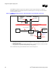
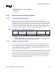
Figure 65 shows the recommended Rset placement.
Figure 65. Rset Resistor Placement
Large via or multiple
vias straight down to
ground plane
IREF ball
Rset
Resistor
Resistor
Solder
Pads
Top Side of
Motherboard
Short, wide route
connecting the
resistor to the IREF
ball
No toggling signals
should be routed near this
reference resistor
128
Ω
, 1%, 1/16W
SMT metal film
resistor
GMCH Chipset
8.1.5. DAC Power Requirements
The DAC requires a 1.5-V supply through its two VCCADAC balls. The two may share a set of
capacitors, 0.1 µF and 0.01 µF, but this connection should have low inductance. Separate analog power
or ground planes are not required for the DAC.
However, since the DAC is an analog circuit, it is particularly sensitive to AC noise seen on its power
rail. Designs should provide as clean and quiet a supply as possible to the VCCA_DAC. Additional