User’s Manual An Intel Socket 478 Processor Based Mainboard Suppor ts FSB400 Supports FSB533 FSB800 FSB800 / / / / DDR266 (PC2100) DDR266/333 (PC2100/PC2700) DDR333 (PC2700) DDR400 (PC3200) TRADEMARK All products and company names are trademarks or registered trademarks of their respective holders. These specifications are subject to change without notice. $ 2,) Manual Revision 1.
DISCLAIMER OF WARRANTIES: THERE ARE NO WARRANTIES WHICH EXTEND BEYOND THE DESCRIPTION ON THE FACE OF THE MANUFACTURER LIMITED WARRANTY. THE MANUFACTURER EXPRESSLY EXCLUDES ALL OTHER WARRANTIES, EXPRESS OR IMPLIED, REGARDING ITS PRODUCTS; INCLUDING ANY IMPLIED WARRANTIES OF MERCHANTABILITY, FITNESS FOR A PARTICULAR PURPOSE OR NONINFRINGEMENT.
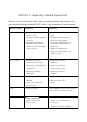
80 Port Frequently Asked Questions Below is a list of some basic POST Codes, possible problems, and solutions. For more detailed information about POST Codes, refer to Appendix D in this manual. P O ST C O D E P r o bl e m So l uti o n FFh o r CFh 1 .B IO S c hip inse rte d 1 . Re inse rt the B IO S inc o rre c tly 2 . Inc o rre c t BIO S update ve rsio n 3 . M ainbo ard pro ble m 4 . Add-o n c ard inse rte d inc o rre c tly. c hip 2 .
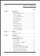
Table of Contents Page Section 1 Introduction Package Contents ...................................................... 1-1 Intel Pentium 4 Processors......................................... 1-2 Chipset Components .................................................. 1-2 Accelerated Graphics Port ......................................... 1-3 Ultra ATA66/100 ........................................................ 1-3 Hardware Monitoring ................................................. 1-3 LAN (Optional) ....
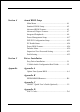
Section 4 Award BIOS Setup Main Menu ................................................................ 4-1 Standard CMOS Setup ............................................... 4-2 Advanced BIOS Features .......................................... 4-3 Advanced Chipset Features ...................................... 4-7 Integrated Peripherals ................................................ 4-9 Power Management Setup ......................................... 4-17 PNP/PCI Configuration Setup ....................
Page Left Blank
Introduction Section 1 INTRODUCTION Package Contents Contents Deluxe Pack Items A. Mainboard I. IEEE 1394 two port cable B. Users manual Other Optional Items C. Floppy drive cable J. USB2.0 port cable D. HDD drive cable or round cable K. S/PDIF Module E. CD and diskette (drivers and If you need the other optional item, please contact dealer for assistance. utilities) F. Game port cable G. I/O Shield H.
Introduction Intel® Pentium® 4 processors The Intel Pentium 4 processor, Intel's most advanced, most powerful processor for desktop PCs and entry-level workstations, is based on Intel NetBurstTM microarchitecture. The Pentium 4 processor is designed to deliver performance across applications and usages where end-users can truly appreciate and experience the performance.
Introduction - Upstream hub link for access to the MCH - 2-Channel Ultra ATA/100 Bus Master IDE controller - USB controller - I/O APIC - SMBus controller - LPC / Flash BIOS interface - PCI 2.3 interface - Integrated System Management Controller Accelerated Graphics Port (AGP) The board provides the AGP 3.0 interface. The AGP interface can support external AGP slot with AGP 8X/4X and Fast Write Transactions. The AGP Interface Specification revision 3.
Introduction Serial ATA The evolutionary serial ATA interface replaces the standard parallel ATA physical storage interface. The serial ATA specification provides scalability and allows future enhancements to the computing platform. Serial technology overcomes performance limits of parallel interface architecture, meeting the escalating need for faster data throughput in servers and storage devices.
Introduction Mainboard Form-Factor The board is designed with ATX form factor - the latest industry standard of chassis. The ATX form factor is essentially a Baby-AT baseboard rotated 90 degrees within the chassis enclosure and a new mounting configuration for the power supply. With these changes the processor is relocated away from the expansion slots, allowing them all to hold full length add-in cards.
Introduction I/O Shield Connector The board is equipped with an I/O back panel (Figure 3). Ensure that your computer case has the appropriate I/O cutout. RJ-45 LAN (Optional) Parallel Port PS/2 Mouse PS/2 Keyboard Line-in/Rear out (Blue) Line-out/Front out (Green) Mic-in/Center&Subwoofer (Pink) COM1 USB2.0 USB2.0 ports ports Figure 3: I/O ports Power-On/Off (Remote) The board has 20-pin ATX and 4-pin ATX12V connectors for power supplies (Figure 4).
Introduction System Block Diagram Figure 5: System Block Diagram Page 1-7
Introduction Page Left Blank Page 1-8
.A=JKHAI Section 2 FEATURES Mainboard Features Processor ® ® ! Socket 478 Intel Pentium 4 processor. Supports Northwood, Prescott or later CPU only, does not support Willamette CPU. ! Supports System Bus and Memory Configurations: FSB400 / DDR266 (PC2100) FSB533 / DDR266/333 (PC2100/PC2700) FSB800 / DDR333 (PC2700) FSB800 / DDR400 (PC3200) * When configured to FSB800/DDR333, adaptive synchronization aligns to the closest FSB to memory clock ratio, setting memory channel to 320MHz.
.A=JKHAI BIOS ! Flash EEPROM with Award BIOS - ACPI v2.0 compliant - S3 (Suspend to DRAM) sleep-state support - SMBIOS (System Management BIOS) v2.
.A=JKHAI - In 2-CH mode, supports Line-In (Blue), Line-Out (Green) and Mic-In (Pink) at rear panel - In 6-CH mode, supports Rear speaker out (Blue), Front speaker out (Green) and Center&Subwoofer speaker out (Pink) at rear panel - Supports CD-In, Aux-In and S/PDIF-In/out interface - Supports Line-out and Mic-In for front panel Peripheral Interfaces ! PS/2 keyboard and mouse ports (at rear panel) ! One Parallel (printer) port (at rear panel) ! Two Serial ports (1 at rear panel) ! Eight USB2.
.A=JKHAI Other Features ! Magic Health a H/W monitoring software utility, for voltages, temperatures and fan-speeds sensing ! EZ Boot An easy way let end-user can choose to boot from hard drive, CD-ROM, floppy, ! Supports exclusive KBPO (Keyboard Power On) function ! Excellent Over clocking capabilities by - subtle voltage tuning on CPU, Memory, AGP - subtle frequency tuning on FSB - Supports complete FSB/Memory and FSB/AGP, PCI Asynchronous scheme for over-clocking ! Supports AGP card 3.
Installation Section 3 INSTALLATION Page 3-1
Installation Mainboard Layout Page 3-2
Installation Easy Installation Procedure The following must be completed before powering on your new system: 3-1. CPU Installation 3-2. Jumper Settings 3-3. System Memory Configuration 3-4. Expansion Slots 3-5. Device Connectors 3-1 CPU Installation Figure 2 Figure 1 Pin 1 Step 1 Step 2 Open the socket by raising the actuation lever. Align pin 1 on the CPU with pin 1 on the CPU socket as shown in the illustration above. The CPU is keyed to prevent incorrect insertion.
Installation Figure 3 Figure 4 Step 3 Step 4 Close the socket by lowering and locking the actuation lever. Apply thermal compound to the top of the CPU and install the heatsink as shown. Figure 5 Figure 6 Step 5 Step 6 Install the cooling fan assembly. Press the two clips in the direction of the arrows shown in Figure 5 to secure the assembly to the CPU socket. Plug the CPU fan into the CPU fan connector. The installation is complete.
Installation 3-2 Jumper Settings JCMOS: Clear CMOS data Jumper If the CMOS data becomes corrupted or you forgot the supervisor or user password, clear the CMOS data to reconfigure the system back to the default values stored in the ROM BIOS. Settings: 1-2: Normal (Default) 2-3: Clear CMOS To CMOS Clear data, please follow the steps below. 1. Turn off the system. 2. Change the jumper from 1-2 to 2-3 position for a few seconds. 3. Replace the jumper on to the 1-2 position. 4.
Installation 3-3 System Memory Configuration Memory Layout The mainboard accommodates four PC2100/PC2700/PC3200 184-pin DIMMs (Dual Inline Memory Modules): Supports up to 4.0GB of 266/333/400MHz DDR SDRAM. Supports two 64-bit wide DDR data channels. Available bandwidth up to 3.2GB/s (DDR400) for single-channel mode and 6.4GB/s (DDR400) in dual-channel mode. Supports non ECC DIMMs. Registered DIMMs not supported. Supports 128-Mb, 256-Mb, 512Mb DDR technologies.
Installation NOTES: When FSB is 400MHz, the mainbaod can support DDR266. When FSB is 533MHz, the mainbaod can support DDR266/333.
Installation DIMM Module Installation Figure 8 displays the notch on the DDR DIMM memory module. DIMMs have 184 pins and one notch that matches with the DDR DIMM socket. DIMM modules are installed by placing the chip firmly into the socket and pressing straight down as shown in figure 9 until the white clips close and the module fits tightly into the DIMM socket (figure 10). CENTER KEY ZONE (2.
Installation 3-4 Expansion Slots AGP Slot The mainboard is equipped with an AGP slot. Make sure you install a card that supports the 1.5V specification. AGP Slot PCI Slots PCI Slots The mainboard is equipped with 5 PCI slots. It supports PCI cards that comply with the PCI specification. Installing an Expansion Card The steps below assume that the mainboard is already installed in the system chassis. 1. Make sure the PC and all other peripheral devices connected to its has been powered down. 2.
Installation AGP Card Installation Caution 1. AGP card component is blocked by DIMM socket lock. 2. AGP slot lock is not locked. 3. AGP card edge connector is not inserted properly. 1. AGP card component is not blocked by DIMM socket lock. 2. AGP slot lock is locked. 3. AGP card edge connector is inserted properly. 1. AGP slot lock is not locked. 2. AGP card edge connector is not inserted properly. 1. AGP slot lock is locked. 2. AGP card edge connector is inserted properly.
Installation 3-5 Connectors Parallel Port PS/2 Mouse PS/2 Keyboard RJ-45 LAN (Optional) Line-in/Rear out (Blue) Line-out/Front out (Green) Mic-in/Center&Subwoofer (Pink) COM1 USB2.0 USB2.0 ports ports Figure 11 - I/O Ports JCPU_FAN JPWR_FAN JCPU_FAN / JPWR_FAN / JSYS_FAN: CPU/Power/Chassis Fan Power Connectors JCPU_FAN: The CPU must be kept cool by using a fan with heatsink. JPWR_FAN: If you are installing an additional fan in the unit, connect the fans connector.
Installation FDD: Floppy Controller Connector (Black) IDE1/2: Ultra DMA-66/100 Primary/Secondary IDE Connector (Blue) IDE3/4: Ultra DMA-66/100 & RAID Primary/ Secondary IDE Connector (Red) Supported by HPT372 chipset, refer to HPT372 RAID Controller users manual for detail information.
Installation CFPA: Front Panel Audio Connector When the jumpers are removed and this connector is used for front panel audio. The type of front panel line-out phone jack is normal close. Without phone plug inserted, the rear panel audio is enabled. With phone plug inserted, the rear panel audio is disabled. MIC_In GND +5V NC Front Line-out-R Rear Line-out-FR Key Rear Line-out-FL Front Line-out-L ' Settings Pins (5-6) & (9-10) Short (default): Only the Onboard Rear Audio Speaker can be used.
Installation GAME1: Game/MIDI connector This port works well with any application that is compatible with the standard PC joystick. COM2: Serial Port Connector The serial port can be used with modems, serial printers, remote display terminals, and other serial device. RTS RI DSR CTS NC 2 10 9 1 DCD TXD Ground RXD DTR SPDIF: Sony/Philips Digital InterFace connector This connector is the digital link between the mainboard and your audio devices, such as CD player, sampler or DAT recorder.
Installation SATA1 / SATA2: Serial ATA Connectors SATA3 / SATA4 (Optional): Sserial ATA Connectors support by Silicom Image Sil3112A chip. SATA2 These connectors enable you to connect Serial ATA devices that conform to the Serial ATA specification.
Installation LED1: 80 Port Debug LED Provides two digits LED light to show why system boots failed for quick and easy optimization. 80 Port Debug 7-segment LED display (Refer to Appendix E for POST codes) USB1/USB2/CUSB3/CUSB4: USB 2.0 ports The mainboard is equipped with eight onboard USB2.0/1.1 ports (4 at rear panel). USB1 It is equipped with a 10-pin connector for connecting 4 additional external USB 2.0/1.1 ports.
Installation CFP: Front Panel Connector " HD_LED This will light when the hard drive is being accessed. " PWR_LED This connects to the power button of the system chassis CFP / CIR / CSPK " RST This switch allows you to reboot without having to power off the system thus prolonginh the life of the power supply or system. " PW_ON This is connected to the power button on the case.
Installation 3-6 External Modem Ring-in Power ON and Keyboard Power ON Functions (KBPO) Modem-Ring Power ON Function The I/O chipset provides the two serial ports with the External Modem Ring-in Power ON function. Once you connect an external modem to COM1 or COM2, the mainboard enables you to turn on the system through remote and host dial-up control. Keyboard Power ON Function The mainboard features a keyboard power on function that enables you to turn on the power supply using a keypress.
Installation 3-7 STR (Suspend To RAM) Function This mainboard supports the STR (Suspend To RAM) power management scheme by maintaining the appropriate power states in the DDR SDRAM interface signals. The power source to the DDR SDRAM must be kept active during STR (ACPI S3). Advanced Configuration Power Interface (ACPI) provides many Energy Saving Features for operating systems that support Instant ON and QuickStart TM function. 1.
Installation 3-8 Supports AGP Card 3.3V Protection The Intel® 865PE chipset supports 1.5 volt AGP graphics cards only. Using a 3.3 volt AGP card in an Intel® 865PE chipset-based board might damage the chipset on an 865PE-equipped mainboard. However, this mainboard features a protection function that prevents the system from powering on when a 3.3V AGP card is inadvertently inserted into the AGP slot. If this happens, we recommend you to follow these steps: Step 1: Remove the 3.
BIOS Section 4 BIOS SETUP Main Menu The ROM BIOS provides a built-in Setup program which allows user to modify the basic system configuration and hardware parameters. The modified data is stored in a battery-backed CMOS, so that data will be retained even when the power is turned off. In general, the information saved in the CMOS RAM will stay unchanged unless there is a configuration change in the system, such as hard drive replacement or a device is added.
BIOS The main menu displays all the major selection items. Select the item you need to reconfigure. The selection is made by moving the cursor (press any direction (arrow key ) to the item and pressing the Enter key. An on-line help message is displayed at the bottom of the screen as the cursor is moved to various items which provides a better understanding of each function. When a selection is made, the menu of the selected item will appear so that the user can modify associated configuration parameters.
BIOS Notes: _ If the hard disk Primary Master/Slave and Secondary Master/Slave are set to Auto, then the hard disk size and model will be auto-detected. _ The Halt On: field is used to determine when to halt the system by the BIOS if an error occurs. _ Floppy 3 Mode support is a mode used to support a special 3.5-inch drive used in Japan. This is a 3.5-inch disk that stores 1.2 MB. The default setting for this is disabled.
BIOS Virus Warning During and after system boot up, any attempt to write to the boot sector or partition table of the hard disk drive halts the system and an error message appears. You should then run an anti-virus program to locate the virus. Keep in mind that this feature protects only the boot sector, not the entire hard drive. The default is Disabled. Enabled: Activates automatically when the system boots up causing a warning message to appear when anything attempts to access the boot sector.
BIOS First /Second/Third/Other Boot Device The BIOS attempts to load the operating system from the devices in the sequence selected in these items. Options: Floppy, LS120, HDD-0, SCSI, CDROM, HDD-1, HDD-2, HDD-3, ZIP100, USB-FDD, USB-ZIP, USB-CDROM, USB-HDD, LAN, Disabled. Boot Other Device When enabled, the system searches all other possible locations for an operating system if it fails to find one in the devices specified under the first, second, and third boot devices. The default is Enabled.
BIOS System: Setup: The system will not boot and access to Setup will be denied unless the correct password is entered at the prompt. The system will boot, but access to Setup will be denied unless the correct password is entered at the prompt. APIC Mode This item allows you to enable APIC (Advanced Programmable Interrupt Controller) functionality. APIC is an Intel chip that provides symmetric multiprocessing (SMP) for its Pentium systems. Options: Enabled, Disabled. HDD S.M.A.R.T. Capability The S.M.A.R.
BIOS 4-3 Advanced Chipset Features Choose the ADVANCED CHIPSET FEATURES option in the CMOS SETUP UTILITY menu to display following menu. Figure 4: Chipset Features Setup DRAM Timing Selectable For setting DRAM Timing, By SPD is follow Intel PC DDR SDRAM Serial Presence Detect Specification. Options: Manual, By SPD. CAS Latency Time Enables you to select the CAS latency time. The value is set at the factory depending on the DRAM installed.
BIOS DRAM RAS# to CAS# Delay This item sets the timing parameters for the system memory such as the CAS (Column Address Strobe) and RAS (Row Address Strobe). The default is by DRAM SPD. Options: 2, 3, 4. DRAM RAS# Precharge This item refers to the number of cycles required to return data to its original location to close the bank or the number of cycles required to page memory before the next bank activate command can be issued. The default is by DRAM SPD. Options: 2, 3, 4.
BIOS 4-4 Integrated Peripherals Figure 5: Integrated Peripherals Notes: If you do not use the Onboard IDE connector, then you will need to set that Onboard Primary PCI IDE: Disabled and Onboard Secondary PCI IDE: Disabled The Onboard PCI IDE cable should be equal to or less than 18 inches (45 cm.). BROADCOM Lan Boot ROM (Optional) Enables and disables the onboard LAN Boot ROM. The default is Disabled. Options: Enabled, Disabled.
BIOS OnChip IDE Device Scroll to OnChip IDE Device and press . The following screen appears: [RAID] IDE HDD Block Mode IDE Block Mode allows the controller to access blocks of sectors rather than a single sector at a time. The default is Enabled. Options: Enabled, Disabled. On-Chip Primary PCI IDE The integrated peripheral controller contains an IDE interface with support for two IDE channels. Select Enabled (default) to activate each channel separately. Options: Enabled, Disabled.
BIOS software both support Ultra DMA-33/66/100, select Auto to enable UDMA mode by BIOS or you can manually disable it. Options: Auto, Disabled. *** On-Chip Serial ATA Setting *** RAID Function Enables the RAID function. When RAID is enabled ("Auto" or "Enabled") Serial ATA ports 0 and 1 will default to "Tertiary" and "Quartenary". Options: Auto, Enabled, Disabled. Note: O/S driver for this feature is available only for Windows XP, please check future updates for other O/S support.
BIOS ! The following screen shows RAID function "Disabled" and on-chip Serial ATA assigned to "Primary". Display only ! The following screen shows RAID function "Disabled" and on-chip Serial ATA assigned to "Secondary".
BIOS Onboard PCI Device Setup Scroll to Onboard PCI Device Setup and press . The following screen appears: USB Controller Enables the all USB controller. Options: Disabled, Enabled. USB 2.0 Controller Enables the EHCI (USB2.0) controller. Options: Disabled, Enabled. USB Keyboard Support Your system contains a Universal Serial Bus (USB) controller and you have a USB keyboard. The default is Auto detect. Options: Auto, Enabled, Disabled.
BIOS Midi Port Address Select an address for the Midi port. Options: 290, 300, 330, Disabled. Midi Port IRQ Select an interrupt for the Midi port. Options: 5, 10. HighPoint Device (Optional) Enables the onboard HighPoint RAID feature. Options: Enabled, Disabled, Auto. Onboard LAN Device (Optional) Enables the onboard LAN feature. Options: Enabled, Disabled. Onboard SIT3112 (Optional) Enables the onboard Serial ATA feature. Options: Enabled, Disabled.
BIOS Onboard I/O Chip Setup Scroll to Onboard I/O Chip Setup and press . The following screen appears: Onboard FDC Controller Select Enabled if your system has a floppy disk controller (FDC) installed on the system board and you wish to use it. If you install add-in FDC or the system has no floppy drive, select Disabled in this field. Options: Enabled, Disabled. Onboard Serial Port 1/2 Select an address and corresponding interrupt for the first and second serial ports.
BIOS Use IR Pins This item allows you to select IR transmission routes, one is RxD2, TxD2 (COM Port) and the other is IR-Rx2Tx2. Options: IR-Rx2Tx2, RxD2, TxD2. Onboard Parallel Port This field allows the user to configure the LPT port. Options: 378/IRQ7, 278/IRQ5, 3BC/IRQ7, Disabled. Parallel Port Mode This field allows the user to select the parallel port mode. Options: SPP, EPP, ECP, ECP+EPP. EPP Mode Select This item allows you to determine the IR transfer mode of onboard I/O chip. Options: EPP1.
BIOS 4-5 Power Management Setup Choose the POWER MANAGEMENT SETUP in the CMOS SETUP UTILITY to display the following screen. This menu allows the user to modify the power management parameters and IRQ signals. In general, these parameters should not be changed unless its absolutely necessary. Figure 6: Power Management ACPI Suspend Type This item allows you to select S1(POS) or S3(STR) function. When set to S3(STR) or S1&S3 the following two fields become available. Options: S1(POS), S3(STR), S1&S3.
BIOS S3 KB Wake-up Function This determines whether or not to enable keyboard/mouse activity to awaken the system from S3(STR) or S1&S3. Options: AnyKey or Mouse, By PowerOn Func., AnyKey, Mouse. POWER ON Function Enables computer power on by keyboard, mouse, or hotkey activity. The default is Hot KEY. Password: Requires you to enter a password when using the keyboard to power on. Set the password in the next field KB Power ON Password.
BIOS Power Management Use this to select your Power Management selection. The default is User define. Max. saving: Maximum power savings. Inactivity period is 1 minute in each mode. Min. saving: Minimum power savings. Inactivity period is 1 hour in each mode. User define: Allows user to define PM Timers parameters to control power saving mode. Video Off Method This option allows you to select how the video will be disabled by the power management.
BIOS HDD Power Down When enabled and after the set time of system inactivity, the hard disk drive will be powered down while all other devices remain active. Options: Disabled, 1 ~ 15 Min. Soft-Off by PWRBTN Use this to select your soft-off function. The default is Instant Off. Instant Off: Turns off the system instantly. Delay 4 Second : Turns off the system after a 4 second delay. If momentary press of button, the system will go into Suspend Mode. Press the power button again to make system back to work.
BIOS ** Reload Global Timer Events ** Primary/Secondary IDE 0/1 Any activity occuring on these channels awakens the system from power savings mode. FDD, COM, LPT Port When enabled, any event occurring on these ports awakens the system from power savings mode. PCI PIRQ[A-D]# When enabled, any event occurring on these PCI slots awakens the system from power savings mode.
BIOS 4-6 PNP/PCI Configuration The PNP/PCI configuration program is for the user to modify the PCI/ISA IRQ signals when various PCI/ISA cards are inserted in the PCI or ISA slots. WARNING: Conflicting IRQs may cause the system to not find certain devices. Figure 7: PNP/PCI Configuration Setup Resources Controlled By Determines what controls system PNP/PCI resources. The default is Auto (ESCD). Manual: PNP Cards resources are controlled manually.
BIOS AGP SLOT / AC97 / PCI Slot 1 ~ Slot 5 / SIL3112A / LAN / HighPoint / Agere 1394 INT Assignment This setting enables the user to specify what IRQ will be assigned to the AGP/ AC97/PCI Slot 1 ~ PCI Slot 5/SIL3112A/LAN/HighPoint/Agere 1394 devices in the chosen slot. Options: Auto, 3, 4, 5, 7,9 ,10, 11, 12, 14 & 15. The default is Auto.
BIOS 4-7 PC Health Status 33oC/91oF 59oC/138oF 0 RPM 0 RPM 0 RPM 1.50V 1.75V 2.50V 4.97V 12.12V -12.28V -5.09V 3.48V 4.89V Figure 8: PC Health Status Show PC Health in POST When this function is enabled the PC Health information is displayed during the POST (Power On Self Test). Options: Enabled, Disabled. CPU Warning Temperature Sets the temperature at the time which the computer will respond to an overheating CPU. The default is Disabled. Options: Disabled, 50OC/122OF ~ 70OC/158OF.
BIOS Vcore (V) The voltage level of the CPU(Vcore). Vdimm(V) The voltage level of the DRAM. VBAT(V) The voltage level of the battery. ± 5V, ± 12V, 5VSB(V) The voltage level of the switching power supply. ACPI Shutdown Temperature This is the temperature that the computer will turn off the power to combat the effects of an overheating system. (requires ACPI to be enabled in Power Management BIOS and ACPI compliant operating system.) The default is Disabled.
BIOS 4-8 Power BIOS Features 66 33 1.75V 1.75V 1.50V 1.50V 2.50V 2.50V Figure 9: Frequency/Voltage Control Watching-Dog Function If you select enabled and overclock fail before POST code 26h, the system will reset automatically by default configuration. Options: Enabled, Disabled. CPU FSB/SPEED Enables you to set the CPU front side bus speed. The default is 100 MHz. Enables you to adjust CPU clock 1MHz by step.
BIOS Note: Overclocking failure will cause system No display problem. At this moment, please press Insert key to back to the initial or default setting to boot up your system. Memory Frequency Enables you to select a ratio of the Double Data Rate Synchronous DRAM to match the installed DRAM frequency 266/333/400MHz. We recommend that you leave this item at the default value. When the FSB is 400MHz the options will display 3:4 =>DDR266.
BIOS AGP/PCI Clock Enables you to set the host clock to work concurrently with the PCI bus or the AGP bus. The default is AUTO. AUTO: The system sets the item automatically. AGP-FSB*2/3 PCI-FSB/3: The system sets the host clock to work with the PCI and AGP bus. By subtle tuning item: The system sets the host clock according to the number produced by the subtle tuning item. AGP/PCI subtle tuning Enables you to set the AGP/PCI frequency, enables you to subtle tuning AGP clock 1MHz by step.
BIOS DIMM Voltage This item allows you to set the DIMM slot voltage. The default is +0.00V. Options: +0.00V to +0.70V in 0.10V increments. We recommend that you leave this at the default value. Clock Generation for EMI Scroll to Clock Generation for EMI and press . The following screen appears: Auto Detect PCI Clk When enabled the mainboard automatically disables the clock source for a PCI slot which does not have a module in it, reducing EMI (ElectroMagnetic Interference). The default is Enabled.
BIOS 4-9 Defaults Menu Selecting Defaults from the main menu shows you two options which are described below Load Fail-Safe Defaults When you press on this item you get a confirmation dialog box: Load Fail-Safe Defaults (Y/N) ? N Pressing Y loads the BIOS default values for the most stable, minimal-performance system operations.
BIOS 4-10 Supervisor/User Password Setting These items are used to install a password. A Supervisor password takes precedence over a User password, and the Supervisor limits the activities of a User. You can set either a supervisor or user password, or both of them: Supervisor password: authorized to enter and change the options of the setup menus. User password: authorized to enter, but not authorized to change the options of the setup menus.
BIOS 4-11 Exiting BIOS Save & Exit Setup Pressing on this item asks for confirmation: Save to CMOS and EXIT (Y/N)? Y Pressing Y stores the selections made in the menus in CMOS a special section of memory that stays on after you turn your system off. The next time you boot your computer, the BIOS configures your system according to the Setup selections stored in CMOS. After saving the values the system is restarted again.
Drivers Installation Section 5 Driver Installation Easy Driver Installation INTEL SPRINGDALE SERIES (865) CHIPSET DRIVER INTEL CHIPSET INF FILES C-MEDIA AUDIO DRIVER (Optional) BROADCOM LAN DRIVER (EXPLORER FOLDER) BROADCOM LAN DRIVER (README.HTM) USB V2.0 (README.HTM) HPT370(A)/372/372N DRIVER (Please install the driver from 3.
Drivers Installation C-Media Audio Configuation Brief Guide Below is list brief guide of C-Media Audio Configuration. For more detailed information, please refer to users manual in the attached CD. You are able to access the control panel from two places: a) The system tray in the right-bottom of your screen. You can click right button of the mouse on it to get an audio-related pop-up menu as follows b) In the Control Panel (Start=>Setting=>Control Panel), double-click CMI Audio Config to open it.
Drivers Installation 1. Speaker output: When you open the 3D Audio Configuration, you will see the default Output tab as the figure below. Speaker Output tab collects main setting/options for analog output to speakers.
Drivers Installation 2. S/PDIF: C-Media driver supports digital S/PDIF output (Sony/Philips Digital InterFace, developed by SONY/PHILIPS to provide a low-distortion digital data transfer between audio devices). There may be an optical or coaxial connector for S/PDIF on your system. When you select S/PDIF tab, you will see the setting page as the figure below. 3. Volume Control: C-Media driver provides the digital volume control for all 6 channels in 3D Audio Configuration.
Drivers Installation 4. Microphone: C-Media driver provides microphone setting in 3D Audio Configuration directly for more convenience. You can control microphone options in the tab though you can also reach them in Microsoft volume control. 5. Xear 3D: C-Media driver now supports Xear 3D- 5.1 Virtual SPEAKER SHIFTER and sound effects. Just click the left button in Xear 3D tab and then the new friendly/fancy graphic user interface will pop up.
Drivers Installation !"Xear 3D - 5.1 Virtual SPEAKER SFIFTER: The SPEAKER SHIFTER block provides an advanced, amazing and considerate feature- dynamically adjustable multi-channel sound system no matter what listening appliance you use and what application you are running. You do NOT have to endure unbalanced speaker placement due to spatial limitation. You can enjoy multi-channel surround sound with even an earphone or usual 2 speakers.
Drivers Installation !" !"Xear 3D - Multi-channel Music Demo: This demo program provides each speaker testing and three 5.1-channel music. You can get feeling about 5.1-channel surround music and use it to test SPEAKER SHIFTER, too. All demo music/sound here will repeat playing if you dont press Stop button. !" !"Xear 3D - Play3D Demo: Xear 3D Advanced Program also provides interesting Play3D demo programs as below.
Drivers Installation 6. Information : There is a C-Media audio-related Information tab in 3D Audio Configuration. You can get a whole picture about the audio chip, driver version, 3D Audio Engine, Microsoft DirectX Version, and Configuration Version itself.
Appendix Appendix A A-1 Update Your System BIOS Download the xxxxx.EXE file corresponding to your model form the our website to an empty directory on your hard disk or floppy. Run the downloaded xxxxx.EXE file and it will self extract. Copy these extracted files to a bootable DOS floppy disk. Note: The DOS floppy disk should contain NO device drivers or other programs. 1. Type A:\AWDFLASH and press Key. 2. You will see the following setup on screen. 3. Please key in the xxxxx.bin BIOS file name.
Appendix 5. Key in File Name to save previous BIOS to file. XXXX XXXXX xxxxx.bin xxxxx.bin 6. Are you sure to program (y/n), please key in [Y] to start the programming. XXXX XXXXX xxxxx.bin xxxxx.bin 7. The programming is finished. XXXX XXXXX xxxxx.
Appendix Appendix B B-1 EEPROM BIOS Remover Do not remove the BIOS chip, unless instructed by a technician and only with a PLCC IC extractor tool. The BIOS socket may be damaged if using an improper method to replace the BIOS chip.
Appendix Page Left Blank B-2
Appendix Appendix C C-1 GHOST 7 Quick User’s Guide (Optional) Installation is very easy. You only need to copy the Ghost7 folder or Ghost.exe to your hard disk. Main Menu Description of Menu Ghost clones and backs up Disk and Partition.
Appendix There are 3 hard disk functions: 1. Disk To Disk (disk cloning) 2. Disk To Image (disk backup) 3. Disk From Image (restore backup) Important! 1. To use this function, the system must have at least 2 disks. Press the Tab key to move the cursor. 2. When restoring to a destination disk, all data in that disk will be completely destroyed. Disk To Disk (Disk Cloning) 1. Select the location of the Source drive. 2. Select the location of the Destination drive. 3.
Appendix Disk To Image (Disk Backup) 1. Select the location of the Source drive. 2. Select the location for storing the backup file. 3. Click OK to display the following confirmation screen. Select Yes to start. Disk From Image (Restore Backup) 1. Select the Restoring file.
Appendix 2. Select the Destination drive of the disk to be restored. 3. When restoring disk backup, set the required partition size as shown in the following figure. 4. Click OK to display the following confirmation screen. Select Yes to start.
Appendix There are 3 partition functions: 1. Partition To Partition (partition cloning) 2. Partition To Image (partition backup) 3. Partition From Image (restore partition) Partition To Partition (Partition Cloning) The basic unit for partition cloning is a partition. Refer to disk cloning for the operating method. Partition To Image (Partition Backup) 1. Select the disk to be backed up. 2. Select the first partition to be backed up. This is usually where the operating system and programs are stored.
Appendix 4. Is the file compressed? There are 3 options: (1) No: do not compress data during backup (2) Fast: Small volume compression (3) High: high ratio compression. File can be compressed to its minimum, but requiring longer execution time. 5. Select Yes to start performing backup. Partition From Image (Restore Partition) 1. Select the backup file to be restored. 2. Select the source partition.
Appendix 3. Select the disk to be restored. 4. Select the partition to be restored. 5. Select Yes to start restoring. Check This function is to check possible error caused by defective FAT or track during backup or restoring.
Appendix How to Reinstall Windows in 2 Minutes This chapter guides you how to setup your computer properly and, if necessary, reinstall Windows in 2 minutes. Ghost provides different methods to complete this task. The following two sections explain how to create an emergency Recover Floppy and Recover CD: Emergency Recover Floppy Divide a hard disk into two partitions. The first partition is to store the operating system and application programs.
Appendix (2) After booting, the screen displays the Menu. Select Backup or Restore: Since the user may install other applications in the future, he/she may alter Autoexec.bat file to back up or restore the user-defined Image file as follows: # Backup Back up Windows and application programs as a file (Recent. gho). Command is: Ghost clone,mode=pdump,src=1:1,dst=d:\Recent.gho -fx sure -rb # Restore Restore types include [General Windows] and [Windows and Application Programs].
Appendix Recover CD The following is a simple guide to create a recover CD: 1. First, create a recover floppy disk contains the following with any copy program such as Easy CD Create (Note 2) : Bootable files (Command.com and Io.sys and MSDOS.SYS) Config.sys (Configuration setup file) Autoexec.bat (Auto-execution batch file) Mscdex.exe (CD-Rom execution file) Ghost.exe (Ghost execution file) Oakcdrom.sys (ATAPI CD-ROM compatible driver) The content of Config.sys is: DEVICE=Oakcdrom.
Appendix Appendix D D-1 POST CODES POST (hex) DESCRIPTION CFh C0h Test CMOS R/W functionality. Early chipset initialization: - Disable shadow RAM - Disable L2 cache (socket 7 or below) - Program basic chipset registers Detect memory - Auto-detection of DRAM size, type and ECC. - Auto-detection of L2 cache (socket 7 or below) Expand compressed BIOS code to DRAM Call chipset hook to copy BIOS back to E000 & F000 shadow RAM.
Appendix 18h 19-1Ah 1Bh 1Ch 1Dh 1Eh 1Fh 20h 21h 22h 23h 24-26h 27h 28h 29h 2A-2Ch 2Dh 2E-32h 33h 34-3Bh 3Ch 3Dh 3Eh 3Fh 40h 41h 42h D-2 Detect CPU information including brand, SMI type (Cyrix or Intel) and CPU level (586 or 686). Reserved Initial interrupts vector table. If no special specified, all H/W interrupts are directed to SPURIOUS_INT_HDLR & S/W interrupts to SPURIOUS_soft_HDLR. Reserved Initial EARLY_PM_INIT switch.
Appendix 43h 44h 45-46h 47h 48h 49h 4A-4Dh 4Eh 4Fh 50h 51h 52h 53-54h 55h 56h 57h 58h 59h 5Ah 5Bh 5Ch 5Dh 5E-5Fh 60h 61-64h 65h 66h 67h 68h 69h 6Ah 6Bh 6Ch 6Dh Test 8259 functionality. Reserved Reserved Initialize EISA slot Reserved 1. Calculate total memory by testing the last double word of each 64K page. 2. Program writes allocation for AMD K5 CPU. Reserved 1. Program MTRR of M1 CPU 2. Initialize L2 cache for P6 class CPU & program CPU with proper cacheable range. 3.
Appendix 6Eh 6Fh 70-72h 73h 74h 75h 76h 77h 78h-79h 7Ah 7B-7Eh 7Fh 80h-81h 82h 83h 84h 85h 86-92h 93h 94h 95h 96h FFh D-4 Reserved 1. Initialize floppy controller 2. Set up floppy related fields in 40:hardware. Reserved (Optional Feature) Enter AWDFLASH.EXE if : -AWDFLASH is found in floppy drive. -ALT+F2 is pressed Reserved Detect & install all IDE devices: HDD, LS120, ZIP, CDROM .. Reserved Detect serial ports & parallel ports. Reserved Detect & install co-processor Reserved 1.