User's Guide Fireface 800 The most powerful FireWire® audio interface ever! ™ TotalMix 24 Bit / 192 kHz 9 ® SyncAlign ZLM ® ® SyncCheck ™ SteadyClock FireWire 800 / 400 Digital I/O System 10 + 16 + 2 Channels Analog / ADAT / SPDIF Interface 24 Bit / 192 kHz Digital Audio 56 x 28 Matrix Router MIDI I/O Stand-Alone Operation MIDI Remote Control Stand-Alone MIDI Controlled Operation
Important Safety Instructions ..................................5 General 1 2 3 4 5 Introduction ...............................................................8 Package Contents .....................................................8 System Requirements ..............................................8 Brief Description and Characteristics.....................8 First Usage - Quick Start 5.1 Connectors and Front Panel ...................................9 5.2 Quick Start ......................................
21 22 Firmware Update..................................................... 41 Configuring the Fireface 22.1 Settings Dialog – General.................................... 42 22.2 Settings Dialog – DDS ......................................... 45 22.3 Clock Modes - Synchronization ........................... 46 22.4 Limit Bandwidth.................................................... 47 23 Mac OS X FAQ 23.1 Round about Driver Installation............................ 48 23.2 MIDI doesn't work .................
32 TotalMix: The Matrix 32.1 Overview ..............................................................76 32.2 Elements of the Matrix View ................................76 32.3 Usage ...................................................................76 32.4 Advantages of the Matrix .....................................77 33 TotalMix Super-Features 33.1 ASIO Direct Monitoring (Windows only) ..............77 33.2 Selection and Group based Operation ................78 33.3 Copy Routings to other Channels .....
Important Safety Instructions ATTENTION! Do not open chassis – risk of electric shock The unit has unisolated live parts inside. No user serviceable parts inside. Refer service to qualified service personnel. Mains • The device must be earthed – never use it without proper grounding • Do not use defective power cords • Operation of the device is limited to the manual • Use same type of fuse only To reduce the risk of fire or electric shock do not expose this device to rain or moisture.
User's Guide Fireface 800 © RME
User's Guide Fireface 800 General User's Guide Fireface 800 © RME 7
1. Introduction Thank you for choosing the Fireface 800. This unique audio system is capable of transferring analog and digital audio data directly to a computer from practically any device. The latest Plug and Play technology guarantees a simple installation, even for the inexperienced user. The numerous unique features and well thought-out configuration dialog puts the Fireface 800 at the very top of the range of computer-based audio interfaces.
5. First Usage - Quickstart 5.1 Connectors and Front Panel The front of the Fireface 800 features an instrument input, microphone inputs and line inputs with gain pots, a stereo headphone output with volume pot, and several status LEDs. MIDI/I indicates MIDI data received by the MIDI input. MIDI/O indicates MIDI data sent to the MIDI output. The Digital State LEDs (WC, SPDIF, ADAT, TCO) indicate a valid input signal separately for each digital input.
5.2 Quick Start After the driver installation (chapter 10 / 20) connect the TRS-jacks or the XLR connectors with the analog signal source. The input sensitivity of the rear inputs can be changed in the Settings dialog (Input Level), assuring the highest signal to noise ratio will be achieved. Try to achieve an optimum input level by adjusting the source itself. Raise the source’s output level until the peak level meters in TotalMix reach about –3 dB.
Optical cable for SPDIF and ADAT operation: OK0050 OK0100 OK0200 OK0300 OK0500 OK1000 Optical cable, TOSLINK, 0.5 m (1.6 ft) Optical cable, TOSLINK, 1 m (3.3 ft) Optical cable, TOSLINK, 2 m (6.6 ft) Optical cable, TOSLINK, 3 m (9.9 ft) Optical cable, TOSLINK, 5 m (16.4 ft) Optical cable, TOSLINK, 10 m (33 ft) Time Code Option to be inserted in the rear slot, adding LTC and Video synchronization inputs to the Fireface, plus a LTC output. TCOFF Time Code Option Fireface 7.
Copyright © Matthias Carstens, 12/2007. Version 2.9 Current driver version: W2k/XP: 2.79, Mac OS X: 2.60a, Firmware 2.66 Although the contents of this User’s Guide have been thoroughly checked for errors, RME can not guarantee that it is correct throughout. RME does not accept responsibility for any misleading or incorrect information within this guide.
CE / FCC Compliance CE This device has been tested and found to comply with the limits of the European Council Directive on the approximation of the laws of the member states relating to electromagnetic compatibility according to RL89/336/EWG and RL73/23/EWG. FCC This equipment has been tested and found to comply with the limits for a Class B digital device, pursuant to Part 15 of the FCC Rules.
User's Guide Fireface 800 © RME
User's Guide Fireface 800 Installation and Operation - Windows User's Guide Fireface 800 © RME 15
9. Hardware Installation Desktop Computer • Use the power cord to connect the Fireface with any suitable power outlet. • Connect computer and Fireface using the supplied 6-pin FireWire cable (IEEE1394a). In case your computer does not have any FireWire port, PCI-cards providing multiple FireWire ports can be added easily. FireWire cards are available in your local computer shop. • Power on the computer. Switch on the Fireface when Windows shows the desktop.
10.2 Driver Update RME driver updates often include a new fireface.inf file. To prevent Windows 2000/XP from using an old fireface.inf, or to copy some of the old driver files, be sure NOT to let Windows search for the driver! Instead tell Windows what to do. Under >Control Panel /System /Device Manager /Sound, Video and Game Controllers /RME Fireface 800/Properties /Driver< you'll find the 'Update Driver' button.
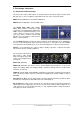
11. Configuring the Fireface 11.1 Settings dialog - General Configuration of the Fireface 800 is done via its own settings dialog.
Buffer Size The setting Buffer Size determines the latency between incoming and outgoing ASIO and GSIF data, as well as affecting system stability (see chapter 13/14). Under Windows MME this setting determines the DMA buffer size (see chapter 12.3). GSIF and MME can be set from 48 to 256 samples. Above 256, only ASIO is effected Inputs Input selection for the channels 1, 7 and 8. Channel 1 can be the front instrument input, or the rear TRS jack, or both simultaneously.
Word Clock Out The word clock output signal usually equals the current sample rate. Selecting Single Speed causes the output signal to always stay within the range of 32 kHz to 48 kHz. So at 96 kHz and 192 kHz sample rate, the output word clock is 48 kHz. SyncCheck SyncCheck indicates whether there is a valid signal (Lock, No Lock) for each input (Word clock, ADAT1, ADAT2, SPDIF), or if there is a valid and synchronous signal (Sync).
11.2 Settings dialog - DDS Usually soundcards and audio interfaces generate their internal clock (master mode) by a quartz. Therefore the internal clock can be set to 44.1 kHz or 48 kHz, but not to a value in between. SteadyClock, RME's sensational Low Jitter Clock System, is based on a Direct Digital Synthesizer (DDS). This superior circuitry can generate nearly any frequency with highest precision.
Application examples DDS allows for a simultaneous change of speed and tune during record and playback. From alignment to other sources up to creative effects – everything is possible.. DDS allows to intentionally de-tune the complete DAW. This way, the DAW can match instruments which have a wrong or unchangeable tuning. DDS allows to define a specific sample rate. This feature can be is useful in case the system randomly changes the sample rate – for unknown reasons.
If several digital devices are to be used simultaneously in a system, they not only have to operate with the same sample frequency but also be synchronous with each other. This is why digital systems always need a single device defined as ‘master’, which sends the same clock signal to all the other (‘slave’) devices. RME’s exclusive SyncCheck technology (first implemented in the Hammerfall) enables an easy to use check and display of the current clock status.
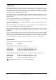
12. Operation and Usage 12.1 Playback The Fireface 800 can play back audio data in supported formats only (sample rate, bit resolution). Otherwise an error message appears (for example at 22 kHz and 8 bit). In the audio application being used, Fireface must be selected as output device. This can often be found in the Options, Preferences or Settings menus under Playback Device, Audio Devices, Audio etc. We strongly recommend switching all system sounds off (via >Control Panel /Sounds<).
12.2 DVD-Playback (AC-3/DTS) AC-3 / DTS When using popular DVD software players like WinDVD and PowerDVD, their audio data stream can be sent to any AC-3/DTS capable receiver using the Fireface's SPDIF output. For this to work, the WDM* SPDIF device of the Fireface 800 has to be selected in >Control Panel/ Sounds and Multimedia/ Audio<. Also check 'use preferred device only'.
12.3 Low Latency under MME (Buffer Size Adjustment) Under Windows 95 or 98, the MME buffer size was nothing to worry about. Latencies below 46 ms were not possible. Meanwhile both computers and operating systems have become much more powerful, and with Windows 2000/XP latencies far lower can be used. SAWStudio and Sonar allowed to use such low settings from the start. Sequoia was updated in version 5.91, WaveLab in version 3.04.
12.4 Notes on WDM The driver offers two devices per stereo pair, like Fireface Analog (1+2) and Fireface Analog (1+2) MME. Fireface Analog (1+2) The devices having no MME at the end are WDM Streaming Devices. WDM Streaming is Microsoft's current driver and audio system, directly embedded into the operating system. WDM Streaming is nearly unusable for professional music purposes, as all data is processed by the so called Kernel Mixer, causing a latency of at least 30 ms.
12.5 Multi-client Operation RME audio interfaces support multi-client operation. This means several programs can be used at the same time. Also all formats, like ASIO, MME and GSIF can be used simultaneously. The use of multi-client operation requires to follow two simple rules: • Multi-client operation requires identical sample rates! I.e. it is not possible to use one software with 44.1 kHz and the other with 48 kHz. • Different software can not use the same channels at the same time.
12.6 Digital Recording Unlike analog soundcards which produce empty wave files (or noise) when no input signal is present, digital interfaces always need a valid input signal to start recording. Taking this into account, RME have included three unique features in the Fireface 800: a comprehensive I/O signal status display showing sample frequency, lock and sync status in the Settings dialog, status LEDs for each input, and the protective Check Input function.
12.7 Analog Recording For recordings via the analog inputs the corresponding record device has to be chosen (Fireface Analog (x+x)). Apart from the three reference levels, the Fireface has no means to change the input level. This would make no sense for the digital inputs, but also for the analog inputs one can do without it.
13.2 Known Problems If a computer does not provide sufficient CPU-power and/or sufficient PCI-bus transfer rates, then drop outs, crackling and noise will appear. We recommend to deactivate all PlugIns to verify that these are not the reason for such effects. Additional hard disk controllers, both on-board and PCI based, aften violate the PCI specs. To achieve the highest throughput they hog the PCI bus, even in their default setting. Thus when working with low latencies heavy drop outs (clicks) are heard.
15. Using more than one Fireface 800 The current driver supports up to three Fireface 800. All units have to be in sync, i.e. have to receive valid sync information (either via word clock or by using AutoSync and feeding synchronized signals). • If one of the Firefaces is set to clock mode Master, all others have to be set to clock mode AutoSync, and have to be synced from the master, for example by feeding word clock.
16. DIGICheck The DIGICheck software is a unique utility developed for testing, measuring and analysing digital audio streams. Although this Windows software is fairly self-explanatory, it still includes a comprehensive online help. DIGICheck 4.52 operates as multi-client ASIO host, therefore can be used in parallel to any software, be it WDM, MME, ASIO or GSIF, with both inputs and outputs (!). The following is a short summary of the currently available functions: • Level Meter.
17. Hotline – Troubleshooting 17.1 General The newest information can always be found on our website www.rme-audio.com, section FAQ, Latest Additions. The input signal cannot be monitored in real-time • ASIO Direct Monitoring has not been enabled, and/or monitoring has been disabled globally. The 8 ADAT channels don’t seem to work • The optical output ADAT2 has been switched to SPDIF.
17.2 Installation After the driver installation the Fireface 800 is found in the Device Manager (), category 'Sound, Video and Gamecontroller'. A double click on 'RME Fireface 800' starts the properties dialog. The well known entry 'Resources' does not exist, because the Fireface is an external device connected to the FireWire Controller. The latter can be used to check interrupt and memory range.
18. Diagrams 18.1 Channel Routing ASIO at 96 kHz This diagram shows the signal paths in ASIO double speed mode (88.2 / 96 kHz). The devices available via the ASIO driver have been designed to avoid conflicts in normal operation, which is why the second ADAT device has been omitted. Record and playback are identical.
18.2 Channel Routing MME at 96 kHz This diagram shows the signal paths in MME double speed mode (88.2 / 96 kHz). The devices available via the MME wave driver have been designed to avoid conflicts in normal operation, which is why the second ADAT device has been omitted. Record and playback are identical.
User's Guide Fireface 800 © RME
User's Guide Fireface 800 Mac OS X – Installation and Operation User's Guide Fireface 800 © RME 39
19. Hardware Installation Desktop Computer • Use the power cord to connect the Fireface with any suitable power outlet. • Connect computer and Fireface using the supplied 6-pin FireWire cable (IEEE1394a). • Power on the computer, then switch on the Fireface. Notebook • Use the power cord to connect the Fireface with any suitable power outlet. • Connect computer and Fireface using the supplied 6-pin FireWire cable (IEEE1394a). • Power on the notebook, then switch on the Fireface 800. 20.
20.2 Driver Update In case of a driver update it's not necessary to remove the old driver first, it will be overwritten during the installation. Exception: driver update from version 1.0. Remove the former Settings dialog and TotalMix from the Login Items, and delete both files from your hard drive! This driver version did not have the features AutoLoad, Dock Lock and AutoRemove.
22. Configuring the Fireface 22.1 Settings Dialog - General Configuring the Fireface is done via its own settings dialog. The panel 'Settings' can be opened by clicking on the fire icon in the dock. The mixer of the Fireface (TotalMix) can be opened by clicking on the mixer icon in the dock. The Fireface’s hardware offers a number of helpful, well thought-of practical functions and options which affect how the card operates - it can be configured to suit many different requirements.
Inputs Input selection for the channels 1, 7 and 8. Channel 1 can be the front instrument input, or the rear TRS jack, or both simultaneously. Channel 7/8 can be the front microphone input, or the rear TRS jack, or both simultaneously. Level In Defines the reference level for the rear analog inputs 1-8. Level Out Defines the reference level for the rear analog outputs 1-8. Instrument Options Drive activates 25 dB additional gain for maximum sustain and brute distortion. Lim.
Clock Mode The unit can be configured to use its internal clock source (Master), or the clock source predefined via Pref. Sync Ref (AutoSync). AutoSync Ref. Displays the current clock source and sample rate of the clock source. Pref. Sync Ref. Used to pre-select the desired clock source. If the selected source isn't available, the system will change to the next available one. The current clock source and sample rate is displayed in the AutoSync Ref display.
22.2 Settings dialog - DDS Usually soundcards and audio interfaces generate their internal clock (master mode) by a quartz. Therefore the internal clock can be set to 44.1 kHz or 48 kHz, but not to a value in between. SteadyClock, RME's sensational Low Jitter Clock System is based on a Direct Digital Synthesizer (DDS). This superior circuitry can generate nearly any frequency with highest precision.
Application examples DDS allows for a simultaneous change of speed and tune during record and playback. From alignment to other sources up to creative effects – everything is possible.. DDS allows to intentionally de-tune the complete DAW. This way, the DAW can match instruments which have a wrong or unchangeable tuning. DDS allows to define a specific sample rate. This feature can be is useful in case the system randomly changes the sample rate – for unknown reasons.
If several digital devices are to be used simultaneously in a system, they not only have to operate with the same sample frequency but also be synchronous with each other. This is why digital systems always need a single device defined as ‘master’, which sends the same clock signal to all the other (‘slave’) devices. RME’s exclusive SyncCheck technology enables an easy to use check and display of the current clock status.
23. Mac OS X FAQ 23.1 Round about Driver Installation The driver with the file suffix gz provided by RME is a compressed TAR archive. TAR bundles multiple files and folders into one file, but does not save memory space nor download time. Both TAR and gz are supported natively by OS X, a double click on the file is all you need to do. Older browsers do not recognize gz as an archive, loading the file as a document. This results in a cryptic looking text within the browser window.
23.3 Supported Sample Rates RME's Mac OS X driver supports all sampling frequencies provided by the hardware. This includes 32 kHz and 64 kHz, and even 128 kHz, 176.4 kHz and 192 kHz for the analog and SPDIF I/Os. But not every software will support all the hardware's sample rates. For example Spark does not display 32 kHz and 64 kHz. The hardware's capabilities can easily be verified in the Audio MIDI Setup. Select Audio devices under Properties of: and choose the Fireface.
Multicard Operation OS X supports more than one audio device. Since 10.4 (Tiger) Core Audio offers the function Aggregate Devices, which allows to combine several devices into one, so that a multi-device operation is possible with any software. The Fireface driver adds a number to each unit, so they are fully accessible in any multicardcapable software. 24. Hotline – Troubleshooting The newest information can always be found on our website www.rme-audio.com, section Support, Macintosh OS.
25. Diagram: Channel Routing at 96 kHz This diagram shows the signal paths in double speed mode (88.2 / 96 kHz). The channels of the second ADAT port have no function anymore in Core Audio, but are used by the hardware to transmit data at double sample rate. Signal routing is identical for record and playback.
User's Guide Fireface 800 © RME
User's Guide Fireface 800 Stand-Alone Operation, Connections and TotalMix User's Guide Fireface 800 © RME 53
26. Stand-alone Operation The Fireface 800 has an internal memory to permanently store all configuration data. These are: Settings dialog Sample rate, clock mode Master/Slave, configuration of the channels and the digital I/Os. TotalMix The complete mixer state. The Fireface loads those settings directly after power-on. A simple, yet useful application is to store the correct clock mode, avoiding wrong clocking and noise disturbances in a complex setup, caused by wrong synchronization.
27. Analog Inputs 27.1 Line Rear The Fireface has eight balanced Line inputs as 1/4" TRS jacks on the back of the unit. The electronic input stage is built in a servo balanced design which handles unbalanced (mono jacks) and balanced (stereo jacks) correctly, automatically adjusting the level reference. When using unbalanced cables with TRS jacks: be sure to connect the 'ring' contact of the TRS jack to ground. Otherwise noise may occur, caused by the unconnected negative input of the balanced input.
27.3 Instrument The instrument input of the Fireface 800 has been optimized especially for guitar and bass. A soft clipping function limits the level from –10 dBFS on, and offers tube-like distortion at full overload. The extra Drive stage adds even more distortion and also increased sustain. The Speaker Emulator gently shapes the sound for an optimal recording experience. LIM The distortion caused by the clipping function of the instrument input is audible.
28. Analog Outputs 28.1 Line The eight short circuit protected, low impedance line outputs are available as 1/4" TRS jacks on the back of the unit. The electronic output stage is built in a servo balanced design which handles unbalanced (mono jacks) and balanced (stereo jacks) correctly.
29. Digital Connections 29.1 ADAT The ADAT optical inputs of the Fireface 800 are fully compatible with all ADAT optical outputs. RME's unsurpassed Bitclock PLL prevents clicks and drop outs even in extreme varipitch operation, and guarantees a fast and low jitter lock to the digital input signal. A usual TOSLINK cable is sufficient for connection. More information on Double Speed (S/MUX) can be found in chapter 37.5.
Special Characteristics of the SPDIF Output Apart from the audio data itself, digital signals in SPDIF or AES/EBU format have a header containing channel status information. False channel status is a common cause of malfunction. The Fireface 800 ignores the received header and creates a totally new one for the output signal. Note that in record or monitor modes, set emphasis bits will disappear.
30. Word Clock 30.1 Word Clock Input and Output SteadyClock guarantees an excellent performance in all clock modes. Based on the highly efficient jitter suppression, the Fireface refreshes and cleans up any clock signal, and provides it as reference clock at the BNC output (see section 37.9). Input The Fireface's transformer isolated word clock input is active when Pref.
30.2 Technical Description and Usage In the analog domain one can connect any device to another device, a synchronization is not necessary. Digital audio is different. It uses a clock, the sample frequency. The signal can only be processed and transmitted when all participating devices share the same clock. If not, the signal will suffer from wrong samples, distortion, crackle sounds and drop outs. AES/EBU, SPDIF and ADAT are self-clocking, an additional word clock connection in principle isn't necessary.
30.3 Cabling and Termination Word clock signals are usually distributed in the form of a network, split with BNC T-adapters and terminated with resistors. We recommend using off-the-shelf BNC cables to connect all devices, as this type of cable is used for most computer networks. You will find all the necessary components (T-adapters, terminators, cables) in most electronics and/or computer stores. The latter usually carries 50 Ohms components.
31. TotalMix: Routing and Monitoring 31.1 Overview The Fireface 800 includes a powerful digital real-time mixer, the Fireface mixer, based on RME’s unique, sample-rate independent TotalMix technology. It allows for practically unlimited mixing and routing operations, with all inputs and playback channels simultaneously, to any hardware outputs. Here are some typical applications for TotalMix: • Setting up delay-free submixes (headphone mixes).
User's Guide Fireface 800 © RME
31.2 The User Interface The visual design of the TotalMix mixer is a result of its capability to route hardware inputs and software playback channels to any hardware output. The Fireface 800 provides 28 input channels, 28 software playback channels, and 28 hardware output channels: 56 channels don't fit on the screen side by side, neither does such an arrangement provide a useful overview. The input channel should be placed above the corresponding output channel.
31.3 Elements of a Channel A single channel consists of various elements: Input channels and playback channels each have a mute and solo button. Below there is the panpot, realized as indicator bar (L/R) in order to save space. In the field below, the present level is displayed in RMS or Peak, being updated about every half a second. Overs (overload) are indicated here by an additional red dot. Next is the fader with a level meter.
Back to AN1/2. Now you can change all the faders of all inputs and playback channels just as you like, thus making any input and playback signals audible via the outputs AN1/2. The panorama can be changed too. Click into the area above the fader and drag the green bar in order to set the panorama between left and right. The level meters of the third row display the level changes in real-time.
Please set Out 4 to a gain of around -20 dB and the pan close to center. Now click onto the routing field. You'll now see two checkmarks, one at 'AN 3+4', the other one at 'AN 7+8'. Click onto 'SPDIF'. The window disappears, fader and pan jump to their initial values, the signal can now be routed to the SPDIF output. You can continue like this until all entries have got a checkmark, i. e. you can send the signal to all outputs simultaneously.
31.7 The Quick Access Panel This section includes additional options, further improving the handling of TotalMix. The Master buttons for Mute and Solo have already been described, they allow for group-based working with these functions. In the View section the single mixer rows can be made visible or invisible. If the inputs are not needed for a pristine playback mix, the whole upper row falls out of the picture after a click on the Input button.
Mouse: The original factory presets can be reloaded by holding down the Ctrlkey and clicking on any preset button. Alternatively the files described above can be renamed, moved to a different directory, or being deleted. Keyboard: Using Ctrl and any number between 1 and 8 (not on the numeric keypad!) will load the corresponding factory default preset. The key Alt will load the user presets instead. When loading a preset file, for example 'Main Monitor AN 1_2 plus headphone mix 3_4.
31.9 The Monitor Panel The Monitor panel provides several options usually found on analog mixing desks. It offers quick access to monitoring functions which are needed all the time in typical studio work. Monitor Main Use the drop down menu to select the hardware outputs where your main monitors are connected to. Dim A click on this button will lower the volume of your main monitor output (see above) by an amount set up in the Preferences dialog (see below).
Main Monitor Dim: Amount of attenuation of the Monitor Main output in dB. Activated by the Dim button in the Monitor panel. Stereo Pan Law The Pan Law can be set to -6 dB, -4.5 dB, -3 dB and 0 dB. The value chosen defines the level attenuation in pan center position. This setting is useful because the ASIO host often supports different pan laws too. Selecting the same value here and in the ASIO host, ASIO Direct Monitoring works perfectly, as both ASIO host and TotalMix use the same pan law.
31.12 Hotkeys In many situations TotalMix can be controlled quickly and comfortably by the keyboard, making the mixer setup considerably easier and faster. The Shift-key for the fine mode for faders and panpots has already been mentioned. The Ctrl-key can do far more than changing the routing pairwise: • Clicking anywhere into the fader area with the Ctrl-key pressed, sets the fader to 0 dB. • Clicking anywhere into the pan area with the Ctrl-key pressed, sets the panorama to meaning Center.
31.13 Menu Options Always on Top: When active (checked) the TotalMix window will always be on top of the Windows desktop. Note: This function may result in problems with windows containing help text, as the TotalMix window will even be on top of those windows, so the help text isn't readable. Deactivate Screensaver: When active (checked) any activated Windows screensaver will be disabled temporarily. Ignore Position: When active, the windows size and position stored in a file or preset will not be used.
31.14 Level Meter The Fireface 800 calculates all the display values Peak, Over and RMS in hardware, in order to be capable of using them independent of the software in use, and to significantly reduce the CPU load. Tip: This feature, the Hardware Level Meter, is used by DIGICheck (Windows only, see chapter 16) to display Peak/RMS level meters of all channels, nearly without any CPU load. The level meters integrated in TotalMix - considering their size - cannot be compared with DIGICheck.
32. TotalMix: The Matrix 32.1 Overview The mixer window of TotalMix looks and operates similar to mixing desks, as it is based on a conventional stereo design. The matrix display presents a different method of assigning and routing channels, based on a single channel or monaural design. The matrix view of the Fireface 800 looks and works like a conventional patchbay, adding functionality way beyond comparable hardware and software soutions.
A gain field marked orange indicates activated mute status. Mute can only be changed in the mixer view. A blue field indicates phase inversion. This state is displayed in the Matrix only, and can only be changed within the Matrix view. Hold down the Shift-key while clicking on an already activated field. Mute overwrites the phase display, blue becomes orange. If mute is deactivated the phase inversion is indicated again. 32.
33.2 Selection and Group-based Operation Click on the white name label of channel 1 and 2 in TotalMix. Be sure to have channel 3's fader set to a different position and click on its label too. All three labels have changed to the colour orange, which means they are selected. Now moving any of these faders will make the other faders move too. This is called 'building a group of faders', or ganging faders, maintaining their relative position.
33.5 Recording a Subgroup (Loopback) TotalMix supports a routing of the subgroup outputs (=hardware outputs, bottom row) to the recording software. Instead of the signal at the hardware input, the signal at the hardware output is sent to the record software. This way, complete submixes can be recorded without an external loopback cable. Also the playback of a software can be recorded by another software. To activate this function, click on the white label in the third row while holding down the Ctrl-key.
Recording a Software's playback In real world application, recording a software's output with another software will show the following problem: The record software tries to open the same playback channel as the playback software (already active), or the playback one has already opened the input channel which should be used by the record software. This problem can easily be solved.
Unfortunately, very often it is not possible within the record software to assign a different input channel to an existing track 'on the fly'. The loopback mode solves this problem elegantly. The routing scheme stays the same, with the input channel 10 sent to any output via TotalMix, to the Compressor, from the Compressor back to any input. Now this input signal is routed directly to output 10, and output 10 is then switched into loopback mode via Ctrl-mouse. As explained in chapter 33.
34. MIDI Remote Control 34.1 Overview TotalMix can be remote controlled via MIDI. It is compatible to the widely spread Mackie Control protocol, so TotalMix can be controlled with all hardware controllers supporting this standard. Examples are the Mackie Control, Tascam US-2400 or Behringer BCF 2000. Additionally, the stereo output faders (lowest row) which are set up as Monitor Main outputs in the Monitor panel can also be controlled by the standard Control Change Volume via MIDI channel 1.
34.3 Setup • Open the Preferences dialog (menu Options or F3). Select the MIDI Input and MIDI Output port where your controller is connected to. • When no feedback is needed (when using only standard MIDI commands instead of Mackie Control protocol) select NONE as MIDI Output. • Check Enable MIDI Control in the Options menu. 34.4 Operation The channels being under MIDI control are indicated by a colour change of the info field below the faders, black turns to yellow.
34.5 Simple MIDI Control The stereo output faders (lowest row) which are set up as Monitor Main outputs in the Monitor panel can also be controlled by the standard Control Change Volume via MIDI channel 1. With this, the main volume of the Fireface is controlable from nearly any MIDI equipped hardware device. Even if you don't want to control all faders and pans, some buttons are highly desired to be available in 'hardware'.
Examples for sending MIDI strings*: - Set input 1 to 0 dB: B0 66 40 - Set input 17 to maximum attenuation: B1 66 0 - Set playback 1 to maximum: B4 66 7F - Set Output 16 to 0 dB setzen B8 75 40 *Note: Sending MIDI strings might require to use programmer's logic for the MIDI channel, starting with 0 for channel 1 and ending with 15 for channel 16. 34.6 Loopback Detection The Mackie Control protocol requires feedback of the received commands, back to the hardware controller.
34.7 Stand-Alone MIDI Control When not connected to a computer, the Fireface 800 can be controlled directly via MIDI. To unlock the special stand-alone MIDI control mode first activate MIDI control in TotalMix (Enable MIDI control), then transfer this state via Flash current mixer state into the unit. Turning this mode off is done in the same way, but with MIDI control deactivated.
In stand-alone MIDI mode, the Mackie Control protocol also gives access to some settings of the Settings dialog: Element: Meaning in Fireface: SOLO Ch. 1 SOLO Ch. 2 SOLO Ch. 3 SOLO Ch. 4 SOLO Ch. 5 SOLO Ch. 6 Input Level Lo Gain Input Level +4 dBu Input Level –10 dBV Output Level Hi Gain Output Level +4 dBu Output Level –10 dBV SOLO Ch. 7 SOLO Ch.
User's Guide Fireface 800 © RME
User's Guide Fireface 800 Technical Reference User's Guide Fireface 800 © RME 89
35. TECH INFO Not all information to and around our products fit in a manual. Therefore RME offers a lot more and detailed information in the Tech Infos. The very latest Tech Infos can be found on our website, section News & Infos, or the directory \rmeaudio.web\techinfo on the RME Driver CD.
36. Technical Specifications 36.1 Analog AD, Line In 1-8, rear • Resolution AD: 24 bit • Signal to Noise ratio (SNR): 110 dB RMS unweighted, 113 dBA • Frequency response @ 44.1 kHz, -0.1 dB: 5 Hz – 20.6 kHz • Frequency response @ 96 kHz, -0.5 dB: 5 Hz – 45.3 kHz • Frequency response @ 192 kHz, -1 dB: 5 Hz - 90 kHz • THD: < -110 dB, < 0.00032 % • THD+N: < -104 dB, < 0.00063 % • Channel separation: > 110 dB • Maximum input level: +19 dBu • Input: 6.
DA, Line Out 1-8, rear • Resolution: 24 bit • Dynamic range (DR): 116 dB, 119 dBA @ 44.1 kHz (unmuted) • Frequency response @ 44.1 kHz, -0.1 dB: 1 Hz – 20.1 kHz • Frequency response @ 96 kHz, -0.5 dB: 1 Hz – 43.5 kHz • Frequency response @ 192 kHz, -1 dB: 1 Hz - 70 kHz • THD: -103 dB, < 0.0007 % • THD+N: -100 dB, < 0.001 % • Channel separation: > 110 dB • Maximum output level: +19 dBu • Output: 6.
36.4 Digital Inputs AES/EBU - SPDIF • 1 x RCA, transformer-balanced, galvanically isolated, according to AES3-1992 • High-sensitivity input stage (< 0.3 Vpp) • SPDIF compatible (IEC 60958) • Accepts Consumer and Professional format, copy protection will be ignored • Lock Range: 27 kHz – 200 kHz • Jitter when synced to input signal: < 1 ns • Jitter suppression: > 30 dB (2.
36.5 Digital Outputs AES/EBU - SPDIF • 1 x RCA, transformer-balanced, galvanically isolated, according to AES3-1992 • Output level Professional 2.6 Vpp, Consumer 1.
37. Technical Background 37.1 Lock and SyncCheck Digital signals consist of a carrier and the data. If a digital signal is applied to an input, the receiver has to synchronize to the carrier clock in order to read the data correctly. To achieve this, the receiver uses a PLL (Phase Locked Loop). As soon as the receiver meets the exact frequency of the incoming signal, it is locked. This Lock state remains even with small changes of the frequency, because the PLL tracks the receiver's frequency.
37.2 Latency and Monitoring The term Zero Latency Monitoring has been introduced by RME in 1998 for the DIGI96 series of audio cards. It stands for the ability to pass-through the computer's input signal at the interface directly to the output. Since then, the idea behind has become one of the most important features of modern hard disk recording.
Therefore, in a digital loopback test a negative offset of about 3 ms occurs. This is no real problem, because this way of working is more than seldom, and usually the offset can be compensated manually within the application. Additionally, keep in mind that even when using the digital I/Os usually at some place an AD- and DA-conversion is involved (no sound without...). Note: Cubase and Nuendo display the latency values signalled from the driver separately for record and playback.
37.4 Number of Channels and Bus Load As explained in chapter 37.3, FireWire Audio does not reach the same performance as PCI audio. On a standard computer with modern single PCI bus, about 100 audio channels can be transmitted per direction (record/playback). Exceeding this limit, any system acitivity - even outside the PCI bus - causes drop outs. Transferring these experiences to FireWire and the Fireface 800 means that besides the number of channels the bus load has to be taken into account too.
37.5 DS - Double Speed When activating the Double Speed mode the Fireface 800 operates at double sample rate. The internal clock 44.1 kHz turns to 88.2 kHz, 48 kHz to 96 kHz. The internal resolution is still 24 bit. Sample rates above 48 kHz were not always taken for granted, and are still not widely used because of the CD format (44.1 kHz) dominating everything. Before 1998 there were no receiver/transmitter circuits available that could receive or transmit more than 48 kHz.
37.7 AES/EBU - SPDIF The most important electrical properties of 'AES' and 'SPDIF' can be seen in the table below. AES/EBU is the professional balanced connection using XLR plugs. The standard is being set by the Audio Engineering Society based on the AES3-1992. For the 'home user', SONY and Philips have omitted the balanced connection and use either Phono plugs or optical cables (TOSLINK). The format called S/P-DIF (SONY/Philips Digital Interface) is described by IEC 60958.
37.8 Noise level in DS / QS Mode The outstanding signal to noise ratio of the Fireface's AD-converters can be verified even without expensive test equipment, by using record level meters of various software. But when activating the DS and QS mode, the displayed noise level will rise from -109 dB to -104 dB at 96 kHz, and –82 dB at 192 kHz. This is not a failure. The software measures the noise of the whole frequency range, at 96 kHz from 0 Hz to 48 kHz (RMS unweighted), at 192 kHz from 0 Hz to 96 kHz.
38. Diagrams 38.
38.2 Connector Pinouts TRS jacks of analog input / output The stereo ¼" TRS jacks of the analog inputs and outputs are wired according to international standards: Tip = + (hot) Ring = – (cold) Sleeve = GND The servo balanced input and output circuitry allows to use monaural TS jacks (unbalanced) with no loss in level. This is the same as when using a TRS-jack with ring connected to ground.