
Computer Hardware User Manual
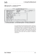
Table Of Contents
- Contents
- 1: Introduction
- Manual Structure
- Manual Features
- If The Motherboard Is Already Installed
- If You Need To Install This Motherboard
- Critical Topics
- Packing List
- Pre-Use Checklist
- 2: Key Features & Components
- Motherboard Layout
- Key Features & Components
- Intel 845G/GL Chipsets
- Winbond Super I/O
- CPU Socket
- System Memory Sockets
- The AGP Slot
- PCI Expansion Slots
- Drive Connectors
- IDE Drive Connectors
- Floppy Disk Drive Connector
- Other Internal Connectors
- ATX Power Connectors
- CPU & System Fan Connectors JCFAN1, JSFAN1, JSFAN2
- CD-In & AUX Audio Connectors JCDIN1 & JAUX1
- Onboard USB Port Connector JUSB1 & Connector JUSB3
- IR Connector JP1
- 6-Channel Audio Option Connector J1
- Smartcard Reader Connector U23
- Memory Stick/Secure Digital Reader Connector JP2
- Smart Panel Audio Connector JAUDIO1
- Front Panel Connector JPANEL1
- Battery Housing
- External I/O Ports
- PS/2 Ports
- Parallel Port
- Serial (COM) Ports
- VGA Port
- USB Ports
- LAN Port
- Audio Jacks & Connectors
- Jumpers
- JCMOS1 Clear CMOS
- JDIMMVOLT1 DDR Voltage
- JUSBV1 USB Standby Voltage
- JPSKMV1 PS/2 Standby Voltage
- Software Features
- Using the Power Installer Disc
- Driver Software
- Utility Software
- 3: Motherboard Configuration
- The Default Configuration
- Hardware Configuration: Jumper Settings
- Jumper JCMOS1: Clear CMOS Memory
- Jumper JDIMMVOLT1: DDR Memory Voltage
- Jumper JUSBV1: USB Standby Voltage
- Jumper JPSKMV1: PS/2 Standby Voltage
- Firmware Configuration: The CMOS Setup Utility
- Using the CMOS Setup Utility
- Reconfiguring the Motherboard
- Hardware Reconfiguration
- Firmware Reconfiguration
- 4: Installing the Motherboard
- Pre-installation Preparation
- Installing A CPU
- Processor Selection
- Installing The Processor
- Installing the Heatsink
- Installing System Memory
- Memory Specifications
- Memory Configuration Options
- Installing Memory Modules
- System Memory Recognition
- Installing the Motherboard in a System Housing
- Motherboard Installation Procedure
- Connecting Front Panel Components
- Completing System Configuration
- 5: System Configuration
- Installing or Connecting Internal Peripherals
- Installing an AGP Card
- AGP Configuration
- Display Drivers
- Connecting Internal Devices
- Connecting IDE Devices
- Connecting a Floppy Disk Drive
- Connecting a Smartcard or MS/SD Reader
- Connecting External System Peripherals
- Connecting a Display Monitor
- Connecting a Keyboard & Mouse
- Configuring the CMOS Setup Utility
- The CMOS Setup Utility User Interface
- Running the CMOS Setup Utility
- CMOS Setup Utility Program Sections
- Standard CMOS Features
- Advanced Boot Options
- Advanced Chipset Features
- Integrated Peripherals
- Power Management Setup
- PnP/PCI Configurations
- PC Health Status
- Frequency/Voltage Setting
- Load Fail-Safe Defaults
- Load Optimized Defaults
- Set Supervisor/User Password
- Save & Exit Setup
- Exit Without Saving
- Installing an OS & Support Software
- Installing an Operating System
- Installing the Support Software
- Installing Windows Drivers
- The Make Driver Utility
- Making a Linux Support Disk
- Installing the Utility Software
- 6: Using the Motherboard
- Using System Features
- Front Panel System Controls & Indicators
- System Controls
- Indicator LEDs
- Additional System Features
- Installing & Configuring An IR Port
- Performance Optimization
- System Memory
- Disk Subsystems
- Processor Upgrades & Adjustments
- Troubleshooting
- Hardware Problems
- General Hardware Troubleshooting
- Hardware Configuration Problems
- Plug and Play Problems
- Replacing the System Configuration Record
- Loading Optimized Defaults
- 7: Technical Specifications

6: Using The Motherboard
User’s Manual
6•3
Indicator LEDs
The motherboard front panel features connector supports
three system status indicator LEDs:
• Power Status LED Indicator
Lights when the system is turned on.
• System Hard Disk Drive Activity LED Indicator
Flashes during hard disk drive access.
• Power Conservation Mode LED Indicator
Lights to indicate the system is in a Suspend state
power conservation mode.
Most system housings will have all of these LEDs mounted
in the housing’s front panel.
Additional System Features
This motherboard supports an optional “Smart Panel”
device. The Smart Panel connectors on the motherboard
connect to cables from the Smart Panel, a device that
mounts in a 5¼-inch bay in the system housing and in-
cludes the following features:
• Compact Flash reader
• Memory Stick reader
• Secure Digital Card reader
• Line Out audio jack
• Microphone jack
• Two Hi-Speed USB 2.0 ports
If you purchase an optional Smart Panel, follow the in-
structions that come with it to install the device.
USB 2.0:
USB 2.0 support is pro-
vided for Windows 2000
and Windows XP. Under
other operating systems
the USB ports will func-
tion as USB 1.1 ports.