
Computer Hardware User Manual
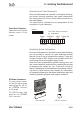
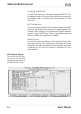
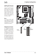
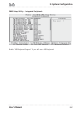
Table Of Contents
- Contents
- 1: Introduction
- Manual Structure
- Manual Features
- If The Motherboard Is Already Installed
- If You Need To Install This Motherboard
- Critical Topics
- Packing List
- Pre-Use Checklist
- 2: Key Features & Components
- Motherboard Layout
- Key Features & Components
- Intel 845G/GL Chipsets
- Winbond Super I/O
- CPU Socket
- System Memory Sockets
- The AGP Slot
- PCI Expansion Slots
- Drive Connectors
- IDE Drive Connectors
- Floppy Disk Drive Connector
- Other Internal Connectors
- ATX Power Connectors
- CPU & System Fan Connectors JCFAN1, JSFAN1, JSFAN2
- CD-In & AUX Audio Connectors JCDIN1 & JAUX1
- Onboard USB Port Connector JUSB1 & Connector JUSB3
- IR Connector JP1
- 6-Channel Audio Option Connector J1
- Smartcard Reader Connector U23
- Memory Stick/Secure Digital Reader Connector JP2
- Smart Panel Audio Connector JAUDIO1
- Front Panel Connector JPANEL1
- Battery Housing
- External I/O Ports
- PS/2 Ports
- Parallel Port
- Serial (COM) Ports
- VGA Port
- USB Ports
- LAN Port
- Audio Jacks & Connectors
- Jumpers
- JCMOS1 Clear CMOS
- JDIMMVOLT1 DDR Voltage
- JUSBV1 USB Standby Voltage
- JPSKMV1 PS/2 Standby Voltage
- Software Features
- Using the Power Installer Disc
- Driver Software
- Utility Software
- 3: Motherboard Configuration
- The Default Configuration
- Hardware Configuration: Jumper Settings
- Jumper JCMOS1: Clear CMOS Memory
- Jumper JDIMMVOLT1: DDR Memory Voltage
- Jumper JUSBV1: USB Standby Voltage
- Jumper JPSKMV1: PS/2 Standby Voltage
- Firmware Configuration: The CMOS Setup Utility
- Using the CMOS Setup Utility
- Reconfiguring the Motherboard
- Hardware Reconfiguration
- Firmware Reconfiguration
- 4: Installing the Motherboard
- Pre-installation Preparation
- Installing A CPU
- Processor Selection
- Installing The Processor
- Installing the Heatsink
- Installing System Memory
- Memory Specifications
- Memory Configuration Options
- Installing Memory Modules
- System Memory Recognition
- Installing the Motherboard in a System Housing
- Motherboard Installation Procedure
- Connecting Front Panel Components
- Completing System Configuration
- 5: System Configuration
- Installing or Connecting Internal Peripherals
- Installing an AGP Card
- AGP Configuration
- Display Drivers
- Connecting Internal Devices
- Connecting IDE Devices
- Connecting a Floppy Disk Drive
- Connecting a Smartcard or MS/SD Reader
- Connecting External System Peripherals
- Connecting a Display Monitor
- Connecting a Keyboard & Mouse
- Configuring the CMOS Setup Utility
- The CMOS Setup Utility User Interface
- Running the CMOS Setup Utility
- CMOS Setup Utility Program Sections
- Standard CMOS Features
- Advanced Boot Options
- Advanced Chipset Features
- Integrated Peripherals
- Power Management Setup
- PnP/PCI Configurations
- PC Health Status
- Frequency/Voltage Setting
- Load Fail-Safe Defaults
- Load Optimized Defaults
- Set Supervisor/User Password
- Save & Exit Setup
- Exit Without Saving
- Installing an OS & Support Software
- Installing an Operating System
- Installing the Support Software
- Installing Windows Drivers
- The Make Driver Utility
- Making a Linux Support Disk
- Installing the Utility Software
- 6: Using the Motherboard
- Using System Features
- Front Panel System Controls & Indicators
- System Controls
- Indicator LEDs
- Additional System Features
- Installing & Configuring An IR Port
- Performance Optimization
- System Memory
- Disk Subsystems
- Processor Upgrades & Adjustments
- Troubleshooting
- Hardware Problems
- General Hardware Troubleshooting
- Hardware Configuration Problems
- Plug and Play Problems
- Replacing the System Configuration Record
- Loading Optimized Defaults
- 7: Technical Specifications

mP4G/mP4GL Motherboard
User’s Manual
5•4
IDE Drive Positioning
Normally the system’s primary hard disk drive should
be in the Primary Master position. If you will use only
the supplied ribbon cable, connect a CD-ROM drive to
the Primary Slave position.
If you obtain an additional IDE ribbon cable, you can
install a second hard disk drive in the Primary Slave po-
sition and install the CD-ROM as the Secondary Master.
This is a good idea if the CD-ROM drive uses a slower
data transfer mode than the hard disk drive.
Follow any instructions that come with the drives to con-
figure and install them. IDE devices generally can be set
to one of three operation modes:
• Master
• Slave
• Cable Select
Many drives come set to the Master setting. If you will
use the drive in a Slave position, you must reconfigure it
as either Slave or use the Cable Select setting to allow the
drives position on the cable to define the mode.
Connecting a Floppy Disk Drive
This motherboard has one Floppy Drive connector for
connecting one or two floppy disk drives. Most computer
systems use one 3.5-inch 1.44MB floppy disk drive. The
drive connector is for a standard floppy drive ribbon cable.
To install a floppy disk drive, connect the drive to the
end of the cable, which is the Drive A: position. Plug the
other end of the cable into the floppy disk drive connec-
tor on the motherboard.
Connecting a Smartcard or MS/SD Reader
This motherboard has connectors for a Smartcard reader
(U23) and a Memory Stick™ or Secure Digital™ memory
card reader (JP2).
To connect any of these devices, follow the intsructions
that come with them. You will need to connect a module
cable to the approriate connector and enable the feature
in the “Integrated Peripherals” section of the CMOS Setup
Utility. The default port settings listed should work.
Cable Select:
Not all drives work prop-
erly with Cable Select
mode. If you try to use this
mode and the drive does
not operate properly, set
the drive to either master
or Slave mode, as appro-
priate for its position on
the cable.