
Computer Hardware User Manual
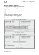
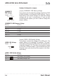
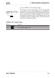
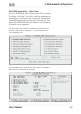
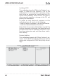
Table Of Contents
- Contents
- 1: Introduction
- Manual Structure
- Manual Features
- If The Motherboard Is Already Installed
- If You Need To Install This Motherboard
- Critical Topics
- Packing List
- Pre-Use Checklist
- 2: Key Features & Components
- Motherboard Layout
- Key Features & Components
- Intel 845G/GL Chipsets
- Winbond Super I/O
- CPU Socket
- System Memory Sockets
- The AGP Slot
- PCI Expansion Slots
- Drive Connectors
- IDE Drive Connectors
- Floppy Disk Drive Connector
- Other Internal Connectors
- ATX Power Connectors
- CPU & System Fan Connectors JCFAN1, JSFAN1, JSFAN2
- CD-In & AUX Audio Connectors JCDIN1 & JAUX1
- Onboard USB Port Connector JUSB1 & Connector JUSB3
- IR Connector JP1
- 6-Channel Audio Option Connector J1
- Smartcard Reader Connector U23
- Memory Stick/Secure Digital Reader Connector JP2
- Smart Panel Audio Connector JAUDIO1
- Front Panel Connector JPANEL1
- Battery Housing
- External I/O Ports
- PS/2 Ports
- Parallel Port
- Serial (COM) Ports
- VGA Port
- USB Ports
- LAN Port
- Audio Jacks & Connectors
- Jumpers
- JCMOS1 Clear CMOS
- JDIMMVOLT1 DDR Voltage
- JUSBV1 USB Standby Voltage
- JPSKMV1 PS/2 Standby Voltage
- Software Features
- Using the Power Installer Disc
- Driver Software
- Utility Software
- 3: Motherboard Configuration
- The Default Configuration
- Hardware Configuration: Jumper Settings
- Jumper JCMOS1: Clear CMOS Memory
- Jumper JDIMMVOLT1: DDR Memory Voltage
- Jumper JUSBV1: USB Standby Voltage
- Jumper JPSKMV1: PS/2 Standby Voltage
- Firmware Configuration: The CMOS Setup Utility
- Using the CMOS Setup Utility
- Reconfiguring the Motherboard
- Hardware Reconfiguration
- Firmware Reconfiguration
- 4: Installing the Motherboard
- Pre-installation Preparation
- Installing A CPU
- Processor Selection
- Installing The Processor
- Installing the Heatsink
- Installing System Memory
- Memory Specifications
- Memory Configuration Options
- Installing Memory Modules
- System Memory Recognition
- Installing the Motherboard in a System Housing
- Motherboard Installation Procedure
- Connecting Front Panel Components
- Completing System Configuration
- 5: System Configuration
- Installing or Connecting Internal Peripherals
- Installing an AGP Card
- AGP Configuration
- Display Drivers
- Connecting Internal Devices
- Connecting IDE Devices
- Connecting a Floppy Disk Drive
- Connecting a Smartcard or MS/SD Reader
- Connecting External System Peripherals
- Connecting a Display Monitor
- Connecting a Keyboard & Mouse
- Configuring the CMOS Setup Utility
- The CMOS Setup Utility User Interface
- Running the CMOS Setup Utility
- CMOS Setup Utility Program Sections
- Standard CMOS Features
- Advanced Boot Options
- Advanced Chipset Features
- Integrated Peripherals
- Power Management Setup
- PnP/PCI Configurations
- PC Health Status
- Frequency/Voltage Setting
- Load Fail-Safe Defaults
- Load Optimized Defaults
- Set Supervisor/User Password
- Save & Exit Setup
- Exit Without Saving
- Installing an OS & Support Software
- Installing an Operating System
- Installing the Support Software
- Installing Windows Drivers
- The Make Driver Utility
- Making a Linux Support Disk
- Installing the Utility Software
- 6: Using the Motherboard
- Using System Features
- Front Panel System Controls & Indicators
- System Controls
- Indicator LEDs
- Additional System Features
- Installing & Configuring An IR Port
- Performance Optimization
- System Memory
- Disk Subsystems
- Processor Upgrades & Adjustments
- Troubleshooting
- Hardware Problems
- General Hardware Troubleshooting
- Hardware Configuration Problems
- Plug and Play Problems
- Replacing the System Configuration Record
- Loading Optimized Defaults
- 7: Technical Specifications
mP4G/mP4GL Series Motherboard
User’s Manual
3•4
Hardware Configuration Jumpers
Jumper JDIMMVOLT1: DDR Memory Voltage
This jumper sets the operating voltage supplied to DDR
DIMMs installed in the board’s DIMM sockets. The de-
fault setting is the normal voltage. The alternate voltage
settings are for use in overclocking. If you are not
overclocking the system, you don’t need to change this
jumper setting.
Jumper JUSBV1: USB Standby Voltage
This jumper controls the voltage to the USB ports. The
default setting is for standard 5V operation. The alter-
nate setting configures the USB ports to also operate with
a standby voltage of 5V. This allows the system to wake
up from an S3 Suspend state. If you anitcipate using this
Suspend mode, you should set this jumper to the alter-
nate setting.
JDIMMVOLT1: DDR Memeory Voltage
Setting Function
Open 2.5-Volt [Default]
Short 1-2 2.6-Volt
Short 3-4 2.7-Volt
Short 5-6 2.8-Volt
Short 7-8 2.9-Volt
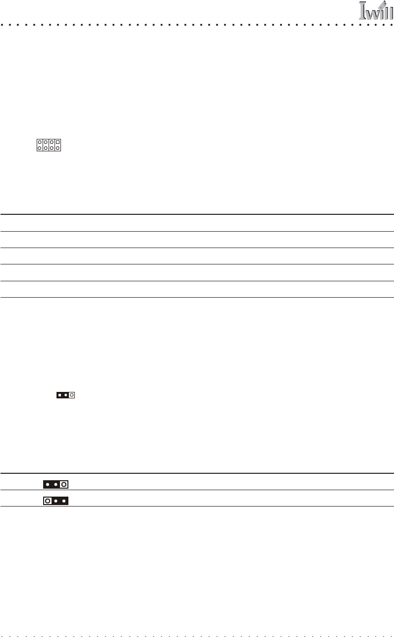
JUSBV1: USB Standby Voltage
Setting Function
Short 1-2 USB Voltage 5-Volt [Default]
Short 2-3 USB Standby Voltage 5-Volt
JDIMMVOLT1
JDIMMVOLT1
DDR Voltage:
Default – 2.5V
Pin 8
Pin 7
Pin 2
Pin 1
JUSBV1
JUSBV1 USB Voltage:
Default – 5V
Pin 1