
Computer Hardware User Manual
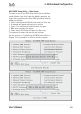
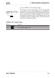
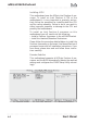
Table Of Contents
- Contents
- 1: Introduction
- Manual Structure
- Manual Features
- If The Motherboard Is Already Installed
- If You Need To Install This Motherboard
- Critical Topics
- Packing List
- Pre-Use Checklist
- 2: Key Features & Components
- Motherboard Layout
- Key Features & Components
- Intel 845G/GL Chipsets
- Winbond Super I/O
- CPU Socket
- System Memory Sockets
- The AGP Slot
- PCI Expansion Slots
- Drive Connectors
- IDE Drive Connectors
- Floppy Disk Drive Connector
- Other Internal Connectors
- ATX Power Connectors
- CPU & System Fan Connectors JCFAN1, JSFAN1, JSFAN2
- CD-In & AUX Audio Connectors JCDIN1 & JAUX1
- Onboard USB Port Connector JUSB1 & Connector JUSB3
- IR Connector JP1
- 6-Channel Audio Option Connector J1
- Smartcard Reader Connector U23
- Memory Stick/Secure Digital Reader Connector JP2
- Smart Panel Audio Connector JAUDIO1
- Front Panel Connector JPANEL1
- Battery Housing
- External I/O Ports
- PS/2 Ports
- Parallel Port
- Serial (COM) Ports
- VGA Port
- USB Ports
- LAN Port
- Audio Jacks & Connectors
- Jumpers
- JCMOS1 Clear CMOS
- JDIMMVOLT1 DDR Voltage
- JUSBV1 USB Standby Voltage
- JPSKMV1 PS/2 Standby Voltage
- Software Features
- Using the Power Installer Disc
- Driver Software
- Utility Software
- 3: Motherboard Configuration
- The Default Configuration
- Hardware Configuration: Jumper Settings
- Jumper JCMOS1: Clear CMOS Memory
- Jumper JDIMMVOLT1: DDR Memory Voltage
- Jumper JUSBV1: USB Standby Voltage
- Jumper JPSKMV1: PS/2 Standby Voltage
- Firmware Configuration: The CMOS Setup Utility
- Using the CMOS Setup Utility
- Reconfiguring the Motherboard
- Hardware Reconfiguration
- Firmware Reconfiguration
- 4: Installing the Motherboard
- Pre-installation Preparation
- Installing A CPU
- Processor Selection
- Installing The Processor
- Installing the Heatsink
- Installing System Memory
- Memory Specifications
- Memory Configuration Options
- Installing Memory Modules
- System Memory Recognition
- Installing the Motherboard in a System Housing
- Motherboard Installation Procedure
- Connecting Front Panel Components
- Completing System Configuration
- 5: System Configuration
- Installing or Connecting Internal Peripherals
- Installing an AGP Card
- AGP Configuration
- Display Drivers
- Connecting Internal Devices
- Connecting IDE Devices
- Connecting a Floppy Disk Drive
- Connecting a Smartcard or MS/SD Reader
- Connecting External System Peripherals
- Connecting a Display Monitor
- Connecting a Keyboard & Mouse
- Configuring the CMOS Setup Utility
- The CMOS Setup Utility User Interface
- Running the CMOS Setup Utility
- CMOS Setup Utility Program Sections
- Standard CMOS Features
- Advanced Boot Options
- Advanced Chipset Features
- Integrated Peripherals
- Power Management Setup
- PnP/PCI Configurations
- PC Health Status
- Frequency/Voltage Setting
- Load Fail-Safe Defaults
- Load Optimized Defaults
- Set Supervisor/User Password
- Save & Exit Setup
- Exit Without Saving
- Installing an OS & Support Software
- Installing an Operating System
- Installing the Support Software
- Installing Windows Drivers
- The Make Driver Utility
- Making a Linux Support Disk
- Installing the Utility Software
- 6: Using the Motherboard
- Using System Features
- Front Panel System Controls & Indicators
- System Controls
- Indicator LEDs
- Additional System Features
- Installing & Configuring An IR Port
- Performance Optimization
- System Memory
- Disk Subsystems
- Processor Upgrades & Adjustments
- Troubleshooting
- Hardware Problems
- General Hardware Troubleshooting
- Hardware Configuration Problems
- Plug and Play Problems
- Replacing the System Configuration Record
- Loading Optimized Defaults
- 7: Technical Specifications

mP4G/mP4GL Series Motherboard
User’s Manual
3•2
The BIOS-Related Jumper
Jumper JCMOS1: Clear CMOS Memory
JCMOS1 is a jumper switch, but it does not set a hard-
ware configuration setting. The BIOS CMOS Setup Utility
creates a system configuration record that is stored in
CMOS memory in the real-time clock chip. If the configu-
ration record data becomes corrupted or is destroyed, or
if the CMOS Setup Utility settings are changed to an un-
usable configuration, the motherboard may not run prop-
erly or at all. JCMOS1 provides a means to delete the
configuration data stored in CMOS memory and reset the
configuration to the CMOS Setup Utility’s Optimized De-
faults.
Follow this procedure to clear CMOS memory. If neces-
sary, refer to the motherboard diagram and key in Chap-
ter 2 for the jumper location.
1. Turn off and unplug the system. Remove the system
housing cover (see documentation if necessary).
2. Set JCMOS1 to the Clear CMOS position by placing
the jumper cap over pins 2 and 3 for one minute.
3. Return the jumper cap to the Normal position.
4. Replace the system housing cover, plug in the sys-
tem and turn it on.
5. Run the CMOS Setup utility and load the Optimized
Defaults. You can then enter any custom settings
you require.
6. Save the settings as you exit the program and restart
the computer.
The system should now operate normally.
JCMOS1: Clear CMOS Memory
Setting Function
Short 1-2 Normal operation [Default]
Short 2-3 Clear CMOS memory – see instructions