
Computer Hardware User Manual
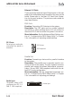
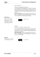
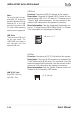
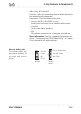
Table Of Contents
- Contents
- 1: Introduction
- Manual Structure
- Manual Features
- If The Motherboard Is Already Installed
- If You Need To Install This Motherboard
- Critical Topics
- Packing List
- Pre-Use Checklist
- 2: Key Features & Components
- Motherboard Layout
- Key Features & Components
- Intel 845G/GL Chipsets
- Winbond Super I/O
- CPU Socket
- System Memory Sockets
- The AGP Slot
- PCI Expansion Slots
- Drive Connectors
- IDE Drive Connectors
- Floppy Disk Drive Connector
- Other Internal Connectors
- ATX Power Connectors
- CPU & System Fan Connectors JCFAN1, JSFAN1, JSFAN2
- CD-In & AUX Audio Connectors JCDIN1 & JAUX1
- Onboard USB Port Connector JUSB1 & Connector JUSB3
- IR Connector JP1
- 6-Channel Audio Option Connector J1
- Smartcard Reader Connector U23
- Memory Stick/Secure Digital Reader Connector JP2
- Smart Panel Audio Connector JAUDIO1
- Front Panel Connector JPANEL1
- Battery Housing
- External I/O Ports
- PS/2 Ports
- Parallel Port
- Serial (COM) Ports
- VGA Port
- USB Ports
- LAN Port
- Audio Jacks & Connectors
- Jumpers
- JCMOS1 Clear CMOS
- JDIMMVOLT1 DDR Voltage
- JUSBV1 USB Standby Voltage
- JPSKMV1 PS/2 Standby Voltage
- Software Features
- Using the Power Installer Disc
- Driver Software
- Utility Software
- 3: Motherboard Configuration
- The Default Configuration
- Hardware Configuration: Jumper Settings
- Jumper JCMOS1: Clear CMOS Memory
- Jumper JDIMMVOLT1: DDR Memory Voltage
- Jumper JUSBV1: USB Standby Voltage
- Jumper JPSKMV1: PS/2 Standby Voltage
- Firmware Configuration: The CMOS Setup Utility
- Using the CMOS Setup Utility
- Reconfiguring the Motherboard
- Hardware Reconfiguration
- Firmware Reconfiguration
- 4: Installing the Motherboard
- Pre-installation Preparation
- Installing A CPU
- Processor Selection
- Installing The Processor
- Installing the Heatsink
- Installing System Memory
- Memory Specifications
- Memory Configuration Options
- Installing Memory Modules
- System Memory Recognition
- Installing the Motherboard in a System Housing
- Motherboard Installation Procedure
- Connecting Front Panel Components
- Completing System Configuration
- 5: System Configuration
- Installing or Connecting Internal Peripherals
- Installing an AGP Card
- AGP Configuration
- Display Drivers
- Connecting Internal Devices
- Connecting IDE Devices
- Connecting a Floppy Disk Drive
- Connecting a Smartcard or MS/SD Reader
- Connecting External System Peripherals
- Connecting a Display Monitor
- Connecting a Keyboard & Mouse
- Configuring the CMOS Setup Utility
- The CMOS Setup Utility User Interface
- Running the CMOS Setup Utility
- CMOS Setup Utility Program Sections
- Standard CMOS Features
- Advanced Boot Options
- Advanced Chipset Features
- Integrated Peripherals
- Power Management Setup
- PnP/PCI Configurations
- PC Health Status
- Frequency/Voltage Setting
- Load Fail-Safe Defaults
- Load Optimized Defaults
- Set Supervisor/User Password
- Save & Exit Setup
- Exit Without Saving
- Installing an OS & Support Software
- Installing an Operating System
- Installing the Support Software
- Installing Windows Drivers
- The Make Driver Utility
- Making a Linux Support Disk
- Installing the Utility Software
- 6: Using the Motherboard
- Using System Features
- Front Panel System Controls & Indicators
- System Controls
- Indicator LEDs
- Additional System Features
- Installing & Configuring An IR Port
- Performance Optimization
- System Memory
- Disk Subsystems
- Processor Upgrades & Adjustments
- Troubleshooting
- Hardware Problems
- General Hardware Troubleshooting
- Hardware Configuration Problems
- Plug and Play Problems
- Replacing the System Configuration Record
- Loading Optimized Defaults
- 7: Technical Specifications
mP4G/mP4GL Series Motherboard
User’s Manual
2•22
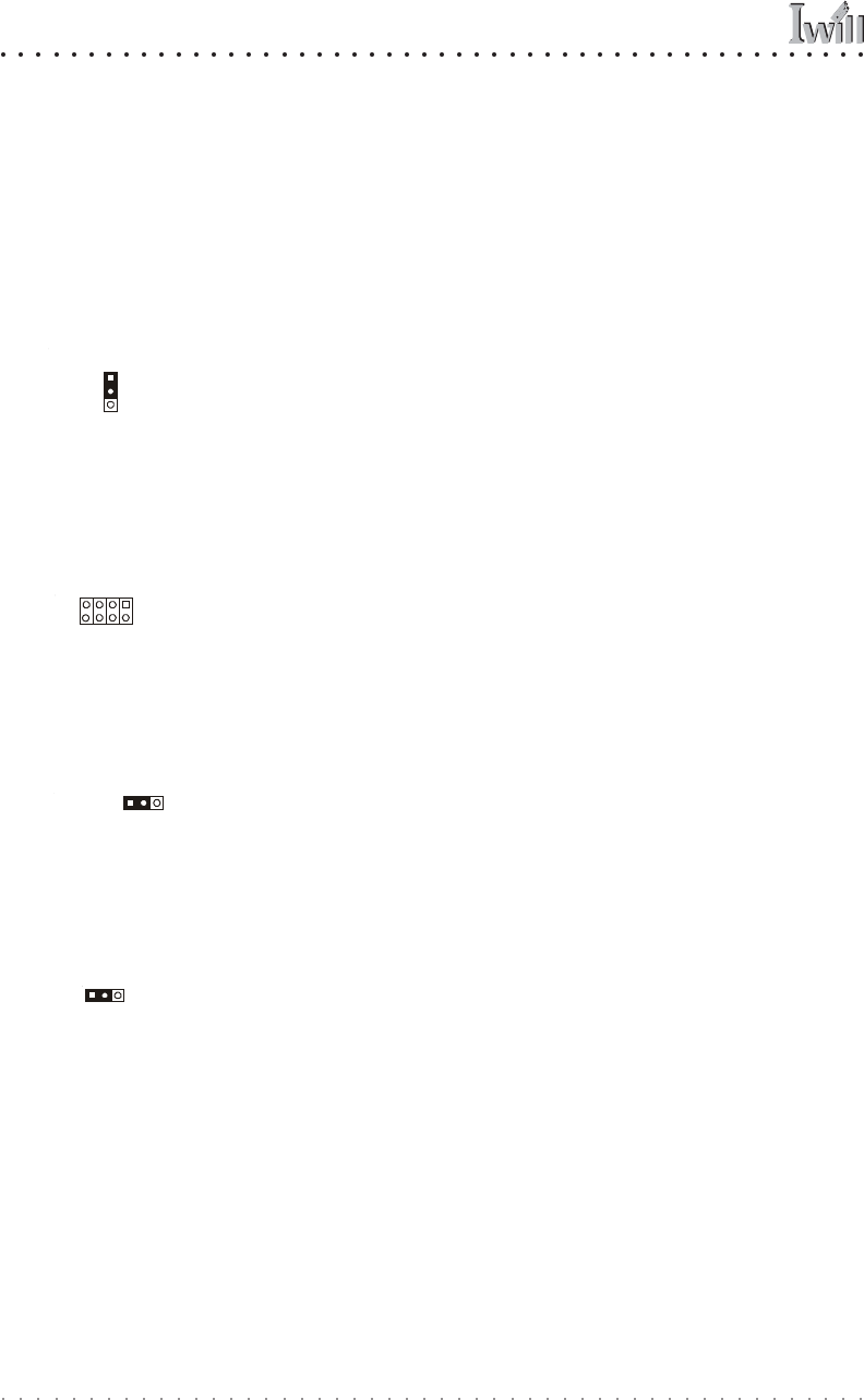
Jumpers
There are five jumper switches on this motherboard.
Jumpers function like switches to establish a hardware
configuration setting.
JCMOS1 Clear CMOS
Function: Clears the CMOS Setup Utility configuration
record stored in the real-time clock’s CMOS memory.
Description: A 3-pin jumper. Default Setting: Normal
More Information: See Chapter 3 for configuration in-
formation and the Troubleshooting section in Chapter 6.
JDIMMVOLT1 DDR Voltage
Function: Sets the voltage supplied to the DIMM DDR
memory sockets.
Description: An 8-pin jumper. Default Setting: 2.5V
More Information: See Chapter 3 for configuration in-
formation and “System Features” in Chapter 6.
JUSBV1 USB Standby Voltage
Function: Sets the voltage status for the USB ports.
Description: A 3-pin jumper. Default Setting: 5V
More Information: See Chapter 3 for information on con-
figuring this jumper.
JPSKMV1 PS/2 Standby Voltage
Function: Sets the voltage status for the PS/2 ports.
Description: A 3-pin jumper. Default Setting: 5V
More Information: See Chapter 3 for information on con-
figuring this jumper.
JDIMMVOLT1
JUSBV1
JPSKMV1
JCMOS1
JCMOS1 Clear CMOS:
Default – Normal
JDIMMVOLT1
DDR Voltage:
Default – 2.5V
JUSBV1 USB Voltage:
Default – 5V
JPSKMV1 PS/2 Voltage:
Default – 5V
Pin 1
Pin 8
Pin 7
Pin 2
Pin 1
Pin 1
Pin 1