
Datasheet


Datasheet 73
Land Listing and Signal Description
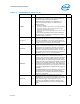
TCK I
TCK (Test Clock) provides the clock input for the
processor Test Bus (also known as the Test Access Port).
TDI I
TDI (Test Data In) transfers serial test data into the
processor. TDI provides the serial input needed for JTAG
specification support.
TDO O
TDO (Test Data Out) transfers serial test data out of the
processor. TDO provides the serial output needed for JTAG
specification support.
TESTHI[12:10] I
TESTHI[12:10] must be connected to a V
TT
power source
through a resistor for proper processor operation. Refer to
Section 2.6 for TESTHI grouping restrictions.
TESTIN1
TESTIN2
I
I
TESTIN1 must be connected to a VTT power source
through a resistor as well as to the TESTIN2 land of the
same socket for proper processor operation.
TESTIN2 must be connected to a VTT power source
through a resistor as well as to the TESTIN1 land of the
same socket for proper processor operation.
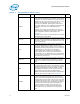
THERMTRIP# O
Assertion of THERMTRIP# (Thermal Trip) indicates the
processor junction temperature has reached a
temperature beyond which permanent silicon damage
may occur. Measurement of the temperature is
accomplished through an internal thermal sensor. Upon
assertion of THERMTRIP#, the processor will shut off its
internal clocks (thus halting program execution) in an
attempt to reduce the processor junction temperature. To
protect the processor its core voltage (V
CC
) must be
removed following the assertion of THERMTRIP#. Intel
also recommends the removal of V
TT
when THERMTRIP#
is asserted.
Driving of the THERMTRIP# signals is enabled within 10
μs of the assertion of PWRGOOD and is disabled on de-
assertion of PWRGOOD. Once activated, THERMTRIP#
remains latched until PWRGOOD is de-asserted. While the
de-assertion of the PWRGOOD signal will de-assert
THERMTRIP#, if the processor’s junction temperature
remains at or above the trip level, THERMTRIP# will again
be asserted within 10 μs of the assertion of PWRGOOD.
1
TMS I
TMS (Test Mode Select) is a JTAG specification support
signal used by debug tools.
TRDY# I
TRDY# (Target Ready) is asserted by the target to
indicate that it is ready to receive a write or implicit
writeback data transfer. TRDY# must connect the
appropriate pins of all FSB agents.
TRST# I
TRST# (Test Reset) resets the Test Access Port (TAP)
logic. TRST# must be driven low during power on Reset.
VCCPLL I
The processor implements an on-die PLL filter solution.
The VCCPLL input is used as a PLL supply voltage.
Table 4-1. Signal Definitions (Sheet 10 of 11)
Name Type Description Notes