
Datasheet


Electrical Specifications
18 Datasheet
NOTES:
1. When the “111111” VID pattern is observed, the voltage regulator output should be
disabled.
2. The VID range includes VID transitions that may be initiated by thermal events, assertion
of the FORCEPR# signal (see Section 5.2.4), Extended HALT state transitions (see
Section 6.2.2), or Enhanced Intel SpeedStep
®
Technology transitions (see Section 6.3).
The Extended HALT state must be enabled for the processor to remain within its
specifications.
3. Once the VRM/EVRD is operating after power-up, if either the Output Enable signal is de-
asserted or a specific VID off code is received, the VRM/EVRD must turn off its output (the
output should go to high impedance) within 500 ms and latch off until power is cycled.
Refer to Voltage Regulator Module (VRM) and Enterprise Voltage Regulator-Down (EVRD)
11.0 Design Guidelines.
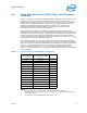
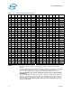
Table 2-3. Voltage Identification Definition
HEX VID6 VID5 VID4 VID3 VID2 VID1 V
CC_MAX
HEX VID6 VID5 VID4 VID3 VID2 VID1 V
CC_MAX
7A1111010.85003C0111101.2375
7811110 00.86253A0111011.2500
7611101 10.8750380111001.2625
7411101 00.8875360110111.2750
7211100 10.9000340110101.2875
7011100 00.9125320110011.3000
6E11011 10.9250300110001.3125
6C1101100.93752E0101111.3250
6A1101010.95002C0101101.3375
6811010 00.96252A0101011.3500
6611001 10.9750280101001.3625
6411001 00.9875260100111.3750
6211000 11.0000240100101.3875
6011000 01.0125220100011.4000
5E10111 11.0250200100001.4125
5C1011101.03751E0011111.4250
5A1011011.05001C0011101.4375
5810110 01.06251A0011011.4500
5610101 11.0750180011001.4625
5410101 01.0875160010111.4750
5210100 11.1000140010101.4875
5010100 01.1125120010011.5000
4E10011 11.1250100010001.5125
4C1001101.13750E0001111.5250
4A1001011.15000C0001101.5375
4810010 01.16250A0001011.5500
4610001 11.1750080001001.5625
4410001 01.1875060000111.5750
4210000 11.2000040000101.5875
4010000 01.2125020000011.6000
3E01111 11.225000000000OFF
1