
Datasheet


Electrical Specifications
16 Datasheet
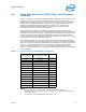
2.4.1 Front Side Bus Frequency Select Signals (BSEL[2:0])
Upon power up, the FSB frequency is set to the maximum supported by the individual
processor. BSEL[2:0] are CMOS outputs which must be pulled up to V
TT
, and are used
to select the FSB frequency. Refer to Table 2-14 for DC specifications. Table 2-2 defines
the possible combinations of the signals and the frequency associated with each
combination. The frequency is determined by the processor(s), chipset, and clock
synthesizer. All FSB agents must operate at the same core and FSB frequency.
2.4.2 PLL Power Supply
An on-die PLL filter solution is implemented on the processor. The V
CCPLL
input is used
for this configuration in Intel
®
Core™2 Extreme processor QX9775 -based platforms.
Refer to Table 2-12 for DC specifications.
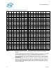
Table 2-2. BSEL[2:0] Frequency Table
BSEL2 BSEL1 BSEL0 Bus Clock Frequency
000 Reserved
001 Reserved
010 Reserved
011 Reserved
100 Reserved
101 Reserved
1 1 0 400 MHz
111 Reserved