
Datasheet

ATX Thermal/Mechanical Design Information
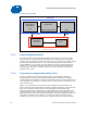
64 Thermal and Mechanical Design Guidelines
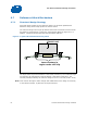
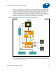
Figure 6-7. Critical Parameters for Interfacing to Reference Clip
Core
Fin Array
Fan
Clip
See Detail A
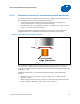
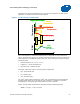
Core
Fin Array
Fan
Clip
See Detail A
Detail A
Fin Array
Clip
Core
1.6 mm
Detail A
Fin Array
Clip
Core
1.6 mm
Detail A
Fin Array
Clip
Core
1.6 mm
Detail A
Fin Array
Clip
Core
1.6 mm
Detail A
Fin Array
Clip
Core
1.6 mm
Detail A
Fin Array
Clip
Core
1.6 mm
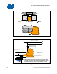
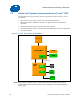
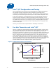
Figure 6-8. Critical Core Dimension
§
R 0.40 mm max
R 0.40 mm max
Φ36.14 +/- 0.10 mm
Gap required to avoid
core surface blemish
during clip assembly.
Recommend 0.3 mm min.
1.00 mm min
2.596 +/- 0.10 mm
Φ38.68 +/- 0.30 mm
1.00 +/- 0.10 mm
Core
NOTE: Dimension from the bottom of the clip to the bottom of the
heatsink core (or base) should be met to enable the required
load from the heatsink clip (i.e., 43 lbf nominal +/- 10 lbf)