® Kontron User's Guide ® ETX® CD Document Revision 1.
This page intentionally left blank
Table of Contents Table of Contents 1 User Information........................................................................................................ 6 1.1 1.2 1.3 1.4 1.5 1.6 2 Introduction .............................................................................................................. 8 2.1 2.2 2.3 3 ETX®-CD ..........................................................................................................8 ETX® Documentation ............................................
Table of Contents 4.5.1 4.5.2 4.6 4.6.1 4.6.2 4.6.3 4.7 4.7.1 4.7.2 4.7.3 4.7.4 5 Special Features ........................................................................................................40 5.1 6 Thermal Management....................................................................................... 41 Heatspreader Dimensions ................................................................................. 41 Important Technology Information .............................................
Table of Contents 8.7 8.8 9 Limitations ..............................................................................................................54 9.1 9.2 10 JIDA Information ............................................................................................ 87 Appendix B: PC Architecture Information ......................................................................88 12.1 12.1.1 12.1.2 12.1.3 12.2 12.2.1 12.2.2 12.2.3 12.2.4 13 Determining the BIOS Version..........................
1 User Information 1 User Information 1.1 About This Document This document provides information about products from Kontron Embedded Modules GmbH and/or its subsidiaries. No warranty of suitability, purpose, or fitness is implied. While every attempt has been made to ensure that the information in this document is accurate, the information contained within is supplied “as-is” and is subject to change without notice.
1 User Information The warranty does not apply to defects resulting from improper or inadequate maintenance or handling by the buyer, unauthorized modification or misuse, operation outside of the product’s environmental specifications or improper installation or maintenance. Kontron Embedded Modules GmbH will not be responsible for any defects or damages to other products not supplied by Kontron Embedded Modules GmbH that are caused by a faulty Kontron Embedded Modules GmbH product. 1.
2 Introduction 2 Introduction 2.1 ETX®-CD Based on the ETX® standard, Kontron’s ETX®-CD, powered by a variety of Intel Pentium core duo processors, is a next-generation embedded module that brings advanced technology to tomorrow’s applications, as well as continuing today’s legacy devices.
2 Introduction 2.2 ETX® Documentation This product manual serves as one of three principal references for an ETX® design. It documents the specifications and features of ETX®-CD. The other two references, which are available from the Kontron Embedded Modules Web site, include: Note: 2.3 ® The ETX® Specification defines the ETX® module form factor, pinout, and signals.
3 Specifications 3 Specifications 3.
3 Specifications System Memory The ETX®-CD uses 200-pin DDR2 Small Outline-Dual Inline Memory Modules (SO-DIMMs). One socket is available for a DDR2-533 or DDR2-667 module up to 2GB capacity. Note: ETX®-CD equipped with the CeleronM423 is not able to drive memory modules faster than DDR2-533.
3 Specifications AC ’97 (Audio): Intel 945GM; ® Up to 20 bit sample resolution ® Multiple sample rates up to 48bit ® Independent bus master logic for dual Microphone Input, dual PCM audio input, PCM audio input, modem input, modem output and S/PDIF output.
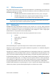
3 Specifications Watchdog timer (WDT): Winbond Super I/O Real-time clock (requires external battery) Block diagram Connector X1 Host Bus Connec-tor J9 Connec-tor J8 Hub Interface Connector X2 Connector X3 Connector X4 Feature Connector J11 3.1.
3 Specifications 3.2 Mechanical Specifications 3.2.1 Dimensions Note: ® 95.0 mm x 114.0 mm ® Height approx. 12 mm (0.4”) The maximum height of electrical components on the bottom side of the module is specified with 2.0mm in the ETX@ specification. On the ETX@-CD the Southbridge is soldered on the bottom side and Intel specified the ICH7 with 2.28mm ± 0.21mm 3.3 Electrical Specifications 3.3.1 Supply Voltage ® 3.3.2 Supply Voltage Ripple ® 3.3.
3 Specifications ETX®-CD Core Duo Processor T2500 CPU Clock Mode Power Consumption 3.3.
3 Specifications 3.4 Environmental Specifications 3.4.1 Temperature Operating: (with Kontron Embedded Modules heat-spreader plate assembly): ® Ambient temperature: 0°C to 60°C ® Maximum heatspreader-plate temperature: 0°C tp 60°C (*) Non-operating: ® -30°C to 85°C See the Thermal Management chapter for additional information. Note: *The maximum operating temperature with the heatspreader plate is the maximum measurable temperature on any spot on the heatspreader’s surface.
3 Specifications Notes: Fans usually shipped with Kontron Embedded Modules GmbH products have 50,000-hour typical operating life. The above estimates assume no fan, but a passive heat sinking arrangement. Estimated RTC battery life (as opposed to battery failures) is not accounted for in the above figures and need to be considered for separately. Battery life depends on both temperature and operating conditions. When the Kontron unit has external power; the only battery drain is from leakage paths.
4 ETX® connectors 4 ETX® connectors The pinouts for ETX® Interface Connectors X1, X2, X3, and X4 are documented for convenient reference. Please see the ETX® Specification and ETX® Design Guide for detailed, design-level information. 4.1 X4 X3 Connector Locations IDE Port Ethernet Power Good/Reset Input ATX PS Control Speaker Battery I2C-Bus SM-Bus VGA LVDS (JILI) Serial Ports PS/2 Keyboard/Mouse IRDA Parallel Port Floppy TV-out ISA Bus PCI Bus USB Audio Serial IRQ 3.3 V for external use (max.
4 ETX® connectors 4.
4 ETX® connectors 4.3.
4 ETX® connectors Pin 51–100: [Power | PCI |USB | AUDIO] Pin 51 52 53 54 55 56 57 58 59 60 61 62 63 64 65 66 67 68 69 70 71 72 73 74 75 76 77 78 79 80 81 82 83 84 85 86 87 88 89 90 91 92 93 94 95 96 97 98 99 100 Note: Signal VCC VCC PAR SERR# GPERR# nc PME# USB2# LOCK# DEVSEL# TRDY# USB3# IRDY# STOP# FRAME# USB2 GND GND AD16 CBE2# AD17 USB3 AD19 AD18 AD20 USB0# AD22 AD21 AD23 USB1# AD24 CBE3# VCC VCC AD25 AD26 AD28 USB0 AD27 AD29 AD30 USB1 PCIRST# AD31 INTC# INTD# INTA# INTB# GND GND Description Power
4 ETX® connectors 4.3.2 Connector X1 Signal Description PCI Bus The implementation of this subsystem complies with the ETX® Specification. Implementation information is provided in the ETX® Design Guide. Refer to the documentation for additional information. USB Three USB host controllers (two 1.1 UHCI and one EHCI high-speed 2.0 controller) are on the Intel® 82801GB south bridge device. The USB controllers comply with both versions 1.1 and 2.0 of the USB standard and are backward compatible.
4 ETX® connectors 4.
4 ETX® connectors 4.4.
4 ETX® connectors Pin 51-100: [Power | ISA] Pin 51 52 53 54 55 56 57 58 59 60 61 62 63 64 65 66 67 68 69 70 71 72 73 74 75 76 77 78 79 80 81 82 83 84 85 86 87 88 89 90 91 92 93 94 95 96 97 98 99 100 Note: Signal VCC VCC SA6 IRQ5 SA7 IRQ6 SA8 IRQ7 SA9 SYSCLK SA10 REFSH# SA11 DREQ1 SA12 DACK1# GND GND SA13 DREQ3 SA14 DACK3# SA15 IOR# SA16 IOW# SA18 SA17 SA19 SMEMR# IOCHRDY AEN VCC VCC SD0 SMEMW# SD2 SD1 SD3 NOWS# DREQ2 SD4 SD5 IRQ9 SD6 SD7 IOCHK# RSTDRV GND GND Description Type Power +5V Power +5V ISA
4 ETX® connectors 4.4.2 Connector X2 Signal Description ISA Bus Slot The implementation of this subsystem complies with the ETX® Specification. Implementation information is provided in the ETX® Design Guide. Refer to the documentation for additional information. Restrictions: Memory Transfer: According to the used LPC 2 ISA solution only memory transfer in the Firmware HUB memory range and with Firmware HUB commands is possible.
4 ETX® connectors 25 27 29 31 33 35 37 39 41 43 45 47 49 Notes: LCDDO9 GND LCDDO4 LCDDO5 GND LCDDO1 LCDDO0 VCC * JILI_DAT JILI_CLK BIASON** COMP** SYNC** 26 28 30 32 34 36 38 40 42 44 46 48 50 LCDDO10 GND LCDDO7 LCDDO6 GND LCDDO3 LCDDO2 VCC * LTGIO0** BLON# DIGON Y** C** *To protect external power lines of peripheral devices, make sure that: - the wires have the right diameter to withstand the maximum available current - the enclosure of the peripheral device fulfils the fire-protection requirements of
4 ETX® connectors 89 91 93 95 97 99 Notes: DCD1# DSR1# CTS1# TXD1 RI1# GND 90 92 94 96 98 100 SLCT# MSCLK MSDAT KBCLK KBDAT GND 89 91 93 95 97 99 DCD1# DSR1# CTS1# TXD1 RI1# GND 90 92 94 96 98 100 WGATE# MSCLK MSDAT KBCLK KBDAT GND *To protect external power lines of peripheral devices, make sure that: - the wires have the right diameter to withstand the maximum available current - the enclosure of the peripheral device fulfils the fire-protection requirements of IEC/EN60950 Kontron User's Guide E
4 ETX® connectors 4.5.
4 ETX® connectors Pin 51–100: [Power | COM |LPT | Floppy | KB/MS/IR] Pin 51 52 53 54 55 56 57 58 59 60 61 62 63 64 65 66 67 68 69 70 71 72 73 74 75 76 77 78 79 80 81 82 83 84 85 86 87 88 89 90 91 92 93 94 95 96 97 98 99 100 Note: Signal LPT | FLPY# nc VCC GND STB# | nc AFD# | DENSEL nc PD7 | nc IRRX ERR# | HDSEL# IRTX PD6 | nc RXD2 INIT# | DIR# GND GND RTS2# PD5 | nc DTR2# SLIN# | STEP# DCD2# PD4 | DSKCHG# DSR2# PD3 | RDATA# CTS2# PD2 | WP# TXD2 PD1 | TRK0# RI2# PD0 | INDEX# VCC VCC RXD1 ACK# | DRV RTS1
4 ETX® connectors 4.5.2 Connector X3 Signal Description VGA Output LVDS Flat Panel Interface (JILI) The user interface for flat panels is the JUMPtec Intelligent LVDS Interface (JILI). The implementation of this subsystem complies with the ETX® Specification. Implementation information is provided in the ETX® Design Guide. Refer to the documentation for additional information. Digital Flat Panel Interface (JIDI) The ETX®-CD does not support the JUMPtec Intelligent Digital Interface (JIDI).
4 ETX® connectors IrDA The ETX®-CD is capable of IrDA SIR operation. This feature is implemented in the Winbond 83627HF. Contact Kontron Embedded Systems for help with this feature. Parallel Port The parallel-communication interface shares signals with the floppy-disk interface. The implementation of this parallel port complies with the ETX® Specification. Implementation information is provided in the ETX® Design Guide. Refer to the documentation for additional information.
4 ETX® connectors 4.6 Connector X4 Subsystems 4.6.
4 ETX® connectors 4.6.
4 ETX® connectors Pin 51-100: [Power | IDE | Ethernet | Misc ] Pin 51 52 53 54 55 56 57 58 59 60 61 62 63 64 65 66 67 68 69 70 71 72 73 74 75 76 77 78 79 80 81 82 83 84 85 86 87 88 89 90 91 92 93 94 95 96 97 98 99 100 Note: Signal SIDE_IOW# PIDE_IOR# SIDE_DRQ PIDE_IOW# SIDE_D15 PIDE_DRQ SIDE_D0 PIDE_D15 SIDE_D14 PIDE_D0 SIDE_D1 PIDE_D14 SIDE_D13 PIDE_D1 GND GND SIDE_D2 PIDE_D13 SIDE_D12 PIDE_D2 SIDE_D3 PIDE_D12 SIDE_D11 PIDE_D3 SIDE_D4 PIDE_D11 SIDE_D10 PIDE_D4 SIDE_D5 PIDE_D10 VCC VCC SIDE_D9 PIDE_D5 S
4 ETX® connectors 4.6.3 Connector X4 Signal Description IDE Ports The IDE host adapter is capable of DMA-133 operation and supports only one single IDE channel which is connected to the primary channel of the ETX® connector X4. Per default it is set to DMA-33, to achieve the best compatibility to most baseboard implementations. Implementation information is provided in the ETX® Design Guide. Refer to those documents for additional information. Configuration: The IDE host adapter is a PCI bus device.
4 ETX® connectors Miscellaneous Circuits Speaker The implementation of the speaker output complies with the ETX® Specification. Implementation information is provided in the ETX® Design Guide. Refer to the documentation for additional information. Battery The implementation of the battery input complies with the ETX® Specification. Implementation information is provided in the ETX® Design Guide. Refer to the documentation for additional information.
4 ETX® connectors ® 45pos,150 mm length, 0.5mm pitch, both ends opposite sides ® Hirose - FH12-45S-0.5SH ® 0.50mm (.020") Pitch FFC/FPC Connector, Horizontal Right Angle, SMT, 45 Circuits Connector 4.7.3 BIOS Requirements There is currently no support for this feature! 4.7.
4 ETX® connectors 44 45 Reserved Reserved Kontron User's Guide ETX CD nc nc 39
5 Special Features 5 Special Features 5.1 Watchdog Timer This feature is implemented in the Winbond 83627HF super I/O. You can configure the Watchdog Timer (WDT) in BIOS setup to start after a set amount of time after power-on boot. The WDT can also be controlled by the JIDA32 Library API (Refer to Appendix F: JIDA Standard). The application software should strobe the WDT to prevent its timeout. Upon timeout, the WDT resets and restarts the system.
6 Design Considerations 6 Design Considerations 6.1 Thermal Management A heat-spreader plate assembly is available from Kontron Embedded Modules GmbH for the ETX®-CD. The heat-spreader plate on top of this assembly is NOT a heat sink. It works as an ETX®-standard thermal interface to use with a heat sink or other cooling device. External cooling must be provided to maintain the heat-spreader plate at proper operating temperatures.
6 Design Considerations Article numbers: 18030-0000-99-0: Heatspreader ETX®-CD, Threaded Hole Stand Off 18030-0000-99-1: Heatspreader ETX®-CD, Through Hole Stand Off Kontron User's Guide ETX CD 42
7 Important Technology Information 7 Important Technology Information The following technological information is designed to give the reader a better understanding of some of features of the ETX®-CD. This information can be referenced when reading the System Resources and BIOS Operation sections that follow. There are also references to additional documentation that will help to develop a better understanding of the technical information described herein. 7.
7 Important Technology Information Automatic mode does not require any additional hardware, software drivers, or interrupt handling routines. Note: With a properly designed thermal solution, the TCC is only active for very short periods, hence processor performance impact is expected to be so minor that it would not be detectable. The Intel® Core Duo® and Core2Duo® processors support the THERMTRIP# signal for catastrophic thermal protection.
7 Important Technology Information declares the temperature threshold the OS uses to decide when to start/stop active cooling devices. See section ETX®-CD onboard Fan connectorfor more information about the ETX®-CD onboard Fan control. Passive Cooling The OS reduces the power consumption of the processor by throttling the processor clock to reduce the temperature of the thermal zone. Passive cooling devices (processor) produce no noise.
7 Important Technology Information 7.5.
7 Important Technology Information 7.5.3 BIOS Settings Feature Option Disabled 15 C 23 C … 55 C 63 C … 119 C Active Trip Point 7.5.4 Description This value controls the temperature of the ACPI active trip point - the point in which the OS will turn on the CPU fan (connector on PCB). If DTS is enabled only values below 97°C are valid.
7 Important Technology Information 7.5.5 Processor Clock Throttling The ACPI OS assesses the optimum CPU performance change necessary to lower the temperature using the following equation: ΔP[%] = TC1(Tn-Tn-1) + TC2(Tn-Tt) ΔP is the performance delta, Tt is the target temperature = passive cooling trip point. The two coefficients TC1 and TC2 and the sampling period TSP are hardware dependent constants the end user must supply (setup options section ACPI Control Submenu).
7 Important Technology Information The following event resumes the system from S3: ® Power Button Kontron User's Guide ETX CD 49
8 System Resources 8 System Resources 8.
8 System Resources In APIC mode: IRQ # Used For Available Available for PCI 0 1 Timer0 Keyboard No No No No 2 Slave 8259 No 3 COM2 No No Yes Note (1) 4 5 No Yes Yes Yes Note (1) Note (2) No Yes Note (1) 7 8 9 10 11 12 13 14 15 COM1 PCI/LPT2 Floppy Drive Controller LPT1 RTC SCI COM3 COM4 PS/2 Mouse FPU IDE0 SATA No No No Yes Yes No No No No Yes No No Yes Yes Yes No No No Note (1) 16 PIRQ[A] For PCI 17 PIRQ[B] For PCI 18 19 20 21 22 23 PIRQ[C] PIRQ[D] PIRQ[E] PIRQ[F] PIRQ[G
8 System Resources 5 6 7 8.3 Yes Yes Yes Memory Area Upper Memory Used for Available C0000h – CFFFFh D0000h – DDFFFh DE000h – DFFFFh E0000h – FFFFFh VGA BIOS No Yes No No 8.4 USB registers System BIOS Comment shadow RAM (ISA bus restriction) I/O Address Map The I/O-port addresses of the ETX®-CD are functionally identical with a standard PC/AT.
8 System Resources D2h D4h 8.8 Clock generator Clock generator Do not use under any circumstances. Do not use under any circumstances. 1 1 JILI-I2C Bus I2C Address Used For Available Comment JIDA-Bus-Nr.
9 Limitations 9 Limitations 9.1 ISA Bus Memory accesses are not supported on the ISA bus. I/O accesses are only supported if they fall into one of the 4 generic decode ranges provided by the chipset. If a plugin ISA card is using registers in I/O space, this address range has to be enabled explicitely using the decode range and size setup items provided under the menu "Advanced" -> "Advanced Chipset Control" -> "ISA Options".
10 BIOS Operation 10 BIOS Operation The module is equipped with a Phoenix BIOS, which is located in an onboard Flash EEPROM. The device has 8-bit access. Faster access (16 bit) is provided by the shadow RAM feature. You can update the BIOS using a Flash utility. 10.1 Determining the BIOS Version To determine the PhoenixBIOS version, immediately press the Pause key on your keyboard as soon as you see the following text display in the upper left corner of your screen: PhoenixBIOS 4.0 Release 6.
10 BIOS Operation Legend Bar Use the keys listed in the legend bar on the bottom to make your selections or exit the current menu. The table below describes the legend keys and their alternates. Key Function or General Help window. Exit menu. Select a menu. ← or → Arrow key ↑ or ↓ Arrow key or or or or <-> or <+> or Select fields in current menu. Cycle cursor up and down.
10 BIOS Operation 10.3 BIOS Setup Menus 10.3.
10 BIOS Operation 10.3.2 Main Menu Feature System Time System Date Legacy Diskette A Legacy Diskette B SMART Device Monitoring Kontron User's Guide ETX CD Option [hh:mm:ss] [mm-dd-yyyy] Disabled 360 kB 1.2 MB 720 kB 1.44 / 1.25 MB 2.88 MB Disabled 360 kB 1.2 MB 720 kB 1.44 / 1.25 MB 2.88 MB Enabled Disabled Description , , or selects field , , or selects field Selects floppy type. Note that 1.25 MB references a 1024 byte sector Japanese media format.
10 BIOS Operation IDE Channels Submenu Feature Type Multi-Sector Transfers LBA Mode Control 32 Bit I/O Transfer Mode Ultra DMA Mode Kontron User's Guide ETX CD Option User Auto None ATAPI Removable CD-ROM IDE Removable Other ATAPI Disabled 2 Sectors 4 Sectors 8 Sectors 16 Sectors Description Specify the number of sectors per block for multiple sector transfers Enabled LBA causes Logical Block Addressing to be used in place of Cylinders, Heads _Sectors.
10 BIOS Operation 10.3.
10 BIOS Operation Advanced Chipset Control Feature Enable Memory Gap Kontron User's Guide ETX CD Option Enabled Disabled Description 61
10 BIOS Operation CPU Control CPU control detects which processor core is used and displays an additional submenu with the detected processor core (yonah, merom, etc.).
10 BIOS Operation Chipset control Feature Memory Throttling Clock generator PCI Clock Run Serial IRQ Quiet Mode Pop Up Mode Enable Pop Down Mode Enable Port 80 h Cycles Kontron User's Guide ETX CD Option Enabled Disabled Description Default Program Enabled Disabled "Program" allows to enable/disable manual change of Spread Spectrum and FSB Controls throttling and bandwidth limiting for the 945 GME If Enabled the Clock Run logic will stop the PCI clocks Enabled: Quiet Mode for SIRQ Disabled: Continu
10 BIOS Operation Integrated Video Feature IGD - Device 2 IGD - Device 2, Function 1 DVMT 3.
10 BIOS Operation ISA Options Feature ISA Bridge 8 Bit I/O recovery 16 Bit I/O recovery Fast Mode Option Description Enabled Disabled 3.5 SYSCLK 4.5 SYSCLK … 10.5 SYSCLK 3.5 SYSCLK 4.5 SYSCLK … 7.
10 BIOS Operation PCI/PNP Configuration Feature PNP OS installed Reset Configuration Data Option ROM Placement PCI IRQ line 1 PCI IRQ line 2 PCI IRQ line 3 PCI IRQ line 4 PCI IRQ line 5 PCI IRQ line 6 PCI IRQ line 7 PCI IRQ line 8 Kontron User's Guide ETX CD Option Description Other Win95 Win98 WinMe Win2000 WinXP No Yes Disabled E000 Extension by PFA Temporary Relocation by PFA E000 Extension by Size Temporary Relocation by Size Auto Select 3 4 5 7 10 11 12 Selects the most used OS "Yes" will cl
10 BIOS Operation PCI/PNP ISA UMB Region Exclusion Feature C000 - CBFF CC00 - CFFF D000 - D3FF D400 - D7FF D800 - DBFF DC00 - DFFF Kontron User's Guide ETX CD Option Description Available Reserved 67
10 BIOS Operation PCI/PNP ISA IRQ Resource Exclusion Feature IRQ 3 IRQ 4 IRQ 5 IRQ 7 IRQ 9 IRQ 10 IRQ 11 Kontron User's Guide ETX CD Option Description Available Reserved 68
10 BIOS Operation Cache Memory Feature Memory Cache Cache System BIOS area Cache Video BIOS area Cache Base 0-512k Cache Base 512k-640k Cache Extended Memory Area Cache A000 - AFFF Cache B000 - BFFF Cache C800 - CBFF Cache CC00 - CFFF Cache D000 - D3FF Cache D400 - D7FF Cache D800 - DBFF Cache DC00 - DFFF Cache E000 - E3FF Cache E400 - E7FF Cache E800 - EBFF Cache EC00 - EFFF Kontron User's Guide ETX CD Option Description Enabled Disabled Write Protect uncached Uncached Write Through Write Protect Wri
10 BIOS Operation I/O Device Configuration Feature Parallel ATA Primary IDE UDMA66/100 Serial ATA SATA Controller Mode Option AHCI Configuration Disable Vacant Ports HD Audio device Option Description Enabled Disabled Enabled Disabled Enabled Disabled Enables/disables the PATA Enables/disables UDMA 66/100 modes Enables/disables SATA Compatible: SATA/PATA devices are driven in legacy mode Enhanced mode: SATA/PATA devices are driven in native mode Enables/disables the Advanced Host Controller Interface
10 BIOS Operation Lan Options Feature LAN Controller #1 Onboard LAN PXE ROM Enable WOL Kontron User's Guide ETX CD Option Description Enabled Disabled Enabled Disabled Enables/disables the PATA Enables/disables the LAN PXE boot ROM Enabled Disabled Enables/disables Wake on LAN 71
10 BIOS Operation Super I/O Controller Options Feature Onboard LPT Serial Port A Base I/O address Interrupt Serial Port B Mode Base I/O address Interrupt External FDC Serial Port C Serial Port D External LPT Kontron User's Guide ETX CD Option Auto Enabled Disabled Description Enables/disables the Parallel Port Enabled Disabled Auto 3F8 2F8 IRQ3 IRQ4 Enables/disables serial port A; Auto: will be initialized when detected Base I/O address of COM port A Selects interrupt of COM port A Enabled Disable
10 BIOS Operation USB ports Feature USB Controller USB UHCI Port 3 USB EHCI Legacy USB Support EHCI Legacy Support Kontron User's Guide ETX CD Option Description Enabled Disabled Enabled Disabled Enabled Disabled Enabled Disabled Enabled Disabled Enables/disables the USB controller Enables/disables USB Port 3 (USB line 5 and 6, which are not accessible) Enables/disables USB 2.0 support Enables/disables USB legacy support Enables/disables USB legacy support in USB 2.
10 BIOS Operation Console Redirection Feature Console Kontron User's Guide ETX CD Option Disabled UCR COM A UCR COM B UCR COM C UCR COM D JRC, Auto Description Controls the serial console redirection.
10 BIOS Operation Keyboard Features Submenu Feature NumLock Key Click Keyboard auto-repeat rate Keyboard auto-repeat delay Kontron User's Guide ETX CD Option Auto On Off Disabled Enabled 30/sec 26.7/sec 21.8/sec 18.5/sec 13.
10 BIOS Operation Hardware Monitor Kontron User's Guide ETX CD 76
10 BIOS Operation Watchdog Settings Feature Mode Timeout Delay Kontron User's Guide ETX CD Option Description Disabled Reset NMI 1sec 5sec 10sec 30sec 1min 5.5min 10.5min 30.5min 1sec 5sec 10sec 30sec 1min 5.5min 10.5min 30.5min Watchdog action Max.
10 BIOS Operation Display Control Feature Display Mode Flat Panel Type Flat Panel Scaling Kontron User's Guide ETX CD Option CRT only LFP only CRT + LFP LFP + EFP VGA 1x18 SVGA 1x18 XGA 1x18 XGA 1x24 SXGA 2x18 SXGA 2x24 UXGA 2x18 Enter PAID Enter FPID Auto Centered Stretched Description CRT: Cathode Ray Tube LFP: LVDS flat panel (JILI) EFP: Embedded flat panel (sDVO) Select [Auto] for JILI or one of the predefined LCD’s Use [Enter PAID] or [Enter FPID] to manually enter panel adapter ID or flat panel
10 BIOS Operation Miscellaneous Submenu Feature Summary Screen Dark Boot Option Dark Boot Logo 0 1 Halt On Errors No Yes QuickBoot Mode Disabled Enabled Extended Memory Testing Floppy check PS/2 Mouse DMA channel Kontron User's Guide ETX CD Description Disabled Extended Disabled Enabled Display system configuration at boot Prevent diagnostic screen output during boot Use -/+ to select the Dark Boot logo 0 – Vendor Logo 1 – Blank screen Determines if errors cause the system to halt Allows the sy
10 BIOS Operation 10.3.4 Security Menu Feature Set Supervisor Password Option [a..z;0..
10 BIOS Operation 10.3.5 Power Menu Feature Enable ACPI Option No Yes Description None S1 S3 S1+S3 S3hot S3cold En/Disable ACPI BIOS (Advance Configuration and Power Interface) After Power Failure Stay Off Last State Power On FACP – RTC S4 Flag Value Disabled Enabled This option allows to selectively enable Sx standby states for ACPI OS. Choosing ‘None’ will force the OS to have only S4 and S5 states.
10 BIOS Operation CPU Thermal Control Circuit Feature Thermal Control Circuit PROCHOT# Enable DTS Enable Active Trip Point Passive Cooling Trip Point Critical Trip Point Kontron User's Guide ETX CD Option Disabled TM1 TM2 TM1 and TM2 Description Enabled Disabled Enabled Disabled Disabled 15 C 23 C … 55 C 63 C … 119 C Disabled 15 C 23 C … 119 C POR 15 C 23 C … 119 C 127 C This function engages the Thermal Control Circuit when enabled Sets the mode of the Thermal Control Circuit Controls the DTS f
10 BIOS Operation 10.3.6 Boot Menu Feature Boot priority order Excluded from boot order Kontron User's Guide ETX CD Option 1:USB Key 2:USB CDROM 3:IDE CE 4:IDE 0 5:IDE 1 6:IDE 2 7:IDE 3 8: IDE 4 IDE5 USB FDC USB HDD USB ZIP USB LS120 PCI SCSI Descpription Keys used to view or configure devices: Up and Down arrows select a device. <+> and <-> moves the device up or down. and specifies the device fixed or removable. exclude or include the device to boot.
10 BIOS Operation 10.3.7 Exit Menu Feature Description Exit System Setup and save your changes to CMOS. Exit utility without saving Setup data to CMOS.
10 BIOS Operation 10.4 Updating or Restoring BIOS Phoenix Phlash16 allows you to update or restore the BIOS with a newer version or restore a corrupt BIOS by using a floppy disk without having to install a new ROM chip. ® Get the Phoenix Phlash16 compressed file, CRDxMODB.ZIP, from the Kontron Embedded Modules GmbH. It contains the following files: File Purpose MAKEBOOT.EXE CRISBOOT.BIN MINIDOS.SYS PHLASH16.EXE WINCRISIS.EXE WINCRISIS.HLP BIOS.
10 BIOS Operation 10.5 Preventing Problems When Updating or Restoring BIOS Updating the BIOS represents a potential hazard. Power failures or fluctuations that may occur during updating the Flash ROM can damage the BIOS code, making the system unbootable. To prevent this potential hazard, many systems come with a boot-block Flash ROM. The boot-block region contains a fail-safe recovery routine.
11 Appendix A: JIDA Standard 11 Appendix A: JIDA Standard Every board with an on-board BIOS extension supports the following function calls, which supply information about the board. Jumptec Intelligent Device Architecture (JIDA) functions are called via Interrupt 15h. Functions include: ® AH=Eah ® AL=function number ® DX=4648h (security word) ® CL=board number (starting with 1) The interrupt returns a CL 0 if a board with the number specified in CL does not exist.
12 Appendix B: PC Architecture Information 12 Appendix B: PC Architecture Information The following sources of information can help you better understand PC architecture. 12.1 Buses 12.1.
12 Appendix B: PC Architecture Information ® 12.2 The PC Handbook: For Engineers, Programmers, and Other Serious PC Users, Sixth Edition, John P. Choisser and John O. Foster, Annabooks, 1997, ISBN 0-929392-36-1 Ports 12.2.1 RS-232 Serial ® EIA232E standard ® The EIA-232-E standard specifies the interface between (for example) a modem and a computer so that they can exchange data. The computer can then send data to the modem, which then sends the data over a telephone line.
12 Appendix B: PC Architecture Information ® The Programmer’s PC Sourcebook, Second Edition, Thom Hogan, Microsoft Press, 1991, ISBN 1-55615-321-X ® Undocumented PC, A Programmer’s Guide to I/O, CPUs, and Fixed Memory Areas, Frank van Gilluwe, Second Edition, Addison-Wesley, 1997, ISBN 0-201-47950-8 Kontron User's Guide ETX CD 90
13 Appendix C: Document Revision 13 Appendix C: Document Revision Rev. Date Author Changes 0.3 17.04.07 UMA 1.0 05.03.08 UMA Created preliminary manual.