GA-945GCM-S2L/ GA-945GCM-S2C LGA775 socket motherboard for Intel® CoreTM processor family/ Intel® Pentium® processor family/Intel® Celeron® processor family User's Manual Rev.
Motherboard GA-945GCM-S2L/GA-945GCM-S2C Aug. 27, 2007 Motherboard GA-945GCM-S2L/ GA-945GCM-S2C Aug.
Copyright © 2008 GIGA-BYTE TECHNOLOGY CO., LTD. All rights reserved. The trademarks mentioned in this manual are legally registered to their respective owners. logo is exclusively licensed to GIGABYTE UNITED INC. by GIGA-BYTE The TECHNOLOGY CO., LTD. GIGABYTE UNITED INC. is designated by GIGA-BYTE TECHNOLOGY CO., LTD as the exclusive global distributor of GIGABYTE branded motherboards. Disclaimer Information in this manual is protected by copyright laws and is the property of GIGABYTE.
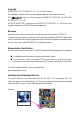
Table of Contents Box Contents ................................................................................................................. 6 Optional Items................................................................................................................. 6 GA-945GCM-S2L/GA-945GCM-S2C Motherboard Layout ............................................ 7 Block Diagram................................................................................................................
Chapter 3 Drivers Installation ...................................................................................... 53 3-1 Installing Chipset Drivers ............................................................................... 53 3-2 3-3 3-4 3-5 Software Applications ..................................................................................... 54 Driver CD Information .................................................................................... 54 Hardware Information ................
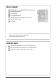
Box Contents GA-945GCM-S2L or GA-945GCM-S2C motherboard Motherboard driver disk User's Manual Quick Installation Guide One IDE cable and one floppy disk drive cable Two SATA 3Gb/s cables I/O Shield • The box contents above are for reference only and the actual items shall depend on product package you obtain. The box contents are subject to change without notice. • The motherboard image is for reference only. Optional Items 2-port USB 2.0 bracket (Part No.
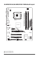
GA-945GCM-S2L/GA-945GCM-S2C Motherboard Layout KB_MS ATX_12V COMA CPU_FAN RTL8111C RTL8101E DDRII1 PCIE_1 BAT CLR_CMOS PCIE_16 MBIOS IT8718 PCI1 PCI2 SPDIF_O Intel ® ICH7 SATAII3 SATAII2 SYS_FAN FDD SATAII1 CI CD_IN CODEC F_USB1F_USB2 Only for GA-945GCM-S2L. Only for GA-945GCM-S2C.
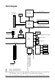
Block Diagram PCIe CLK (100 MHz) D-Sub CPU CLK+/(333 (Note 1)/266/200/133 MHz) LGA775 Processor Host Interface PCI Express x16 Dual Channel Memory Intel® 945GC GMCH CLK (333 (Note 1)/266/200/133 MHz) LAN 1 PCI Express x1 RJ45 PCIe CLK (100 MHz) x1 DDR2 667/533/400 MHz(Note 2) BIOS RTL8111C RTL8101E PCI Express Bus ATA-100/66/33 IDE Channel 4 SATA 3Gb/s Intel® ICH7 8 USB Ports PCI Bus Floppy IT8718 COM Port PCI CLK (33 MHz) SPDIF Out MIC(Center/Subwoofer Speaker Out) Line-Out(Front S
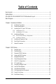
Chapter 1 Hardware Installation 1-1 Installation Precautions The motherboard contains numerous delicate electronic circuits and components which can become damaged as a result of electrostatic discharge (ESD). Prior to installation, carefully read the user's manual and follow these procedures: • • • • • • • • • Prior to installation, do not remove or break motherboard S/N (Serial Number) sticker or warranty sticker provided by your dealer. These stickers are required for warranty validation.
1-2 Product Specifications CPU Support for an Intel® Core 2 Extreme processor/ Intel® Core 2 Duo processor/Intel® Pentium® D processor/ Intel ® Pentium ® 4 processor/ Intel ® Celeron ® processor in the LGA 775 package (Go to GIGABYTE's website for the latest CPU support list.) Support for Intel ® Hyper-Threading Technology L2 cache varies with CPU 1333 (Note 1)/1066/800/533 MHz FSB North Bridge: Intel ® 945GC Express Chipset South Bridge: Intel® ICH7 2 x 1.
Internal Connectors Back Panel Connectors I/O Controller Hardware Monitor BIOS 1 x 24-pin ATX main power connector 1 x 4-pin ATX 12V power connector 1 x floppy disk drive connector 1 x IDE connector 4 x SATA 3Gb/s connectors 1 x CPU fan header 1 x system fan header 1 x front panel header 1 x front panel audio header 1 x CD In connector 1 x S/PDIF Out header 2 x USB 2.0/1.
Unique Features Bundled Software Operating System Form Factor Support for @BIOS Support for Download Center Support for Q-Flash Support for EasyTune (Note 4) Support for Xpress Install Support for Xpress Recovery2 Support for Virtual Dual BIOS Norton Internet Security (OEM version) Support for Microsoft® Windows® Vista/XP Micro ATX form factor; 24.4cm x 19.3cm (Note 1) Enable use of a Core TM 2 CPU with 1333 MHz FSB through overclocking.
1-3 Installing the CPU and CPU Cooler Read the following guidelines before you begin to install the CPU: • Make sure that the motherboard supports the CPU. (Go to GIGABYTE's website for the latest CPU support list.) • Always turn off the computer and unplug the power cord from the power outlet before installing the CPU to prevent hardware damage. • Locate the pin one of the CPU. The CPU cannot be inserted if oriented incorrectly.
B. Follow the steps below to correctly install the CPU into the motherboard CPU socket. Before installing the CPU, make sure to turn off the computer and unplug the power cord from the power outlet to prevent damage to the CPU. CPU Socket Lever Step 1: Completely raise the CPU socket lever. Step 2: Lift the metal load plate from the CPU socket. (DO NOT touch socket contacts.) Step 3: Remove the protective socket cover from the load plate.
1-3-2 Installing the CPU Cooler Follow the steps below to correctly install the CPU cooler on the motherboard. (The following procedure uses Intel ® boxed cooler as the example cooler.) Male Push Pin Direction of the Arrow Sign on the Male Push Pin The Top of Female Push Pin Female Push Pin Step 1: Apply an even and thin layer of thermal grease on the surface of the installed CPU. Step 2: Before installing the cooler, note the direction of the arrow sign on the male push pin.
1-4 Installing the Memory Read the following guidelines before you begin to install the memory: • Make sure that the motherboard supports the memory. It is recommended that memory of the same capacity, brand, speed, and chips be used. (Go to GIGABYTE's website for the latest memory support list.) • Always turn off the computer and unplug the power cord from the power outlet before installing the memory to prevent hardware damage. • Memory modules have a foolproof design.
1-4-2 Installing a Memory Before installing a memory module , make sure to turn off the computer and unplug the power cord from the power outlet to prevent damage to the memory module. DDR2 DIMMs are not compatible to DDR DIMMs. Be sure to install DDR2 DIMMs on this motherboard. Notch DDR2 DIMM A DDR2 memory module has a notch, so it can only fit in one direction. Follow the steps below to correctly install your memory modules in the memory sockets. Step 1: Note the orientation of the memory module.
1-5 Installing an Expansion Card Read the following guidelines before you begin to install an expansion card: • Make sure the motherboard supports the expansion card. Carefully read the manual that came with your expansion card. • Always turn off the computer and unplug the power cord from the power outlet before installing an expansion card to prevent hardware damage. PCI Express x16 Slot PCI Slot PCI Express x1 Slot Follow the steps below to correctly install your expansion card in the expansion slot.
1-6 Back Panel Connectors PS/2 Keyboard and PS/2 Mouse Port Use the upper port (green) to connect a PS/2 mouse and the lower port (purple) to connect a PS/2 keyboard. Parallel Port Use the parallel port to connect devices such as a printer, scanner and etc. The parallel port is also called a printer port. Serial Port Use the serial port to connect devices such as a mouse, modem or other peripherals. D-Sub Port The D-Sub port supports a 15-pin D-Sub connector.
RJ-45 LAN Port The Fast Ethernet LAN port provides Internet connection at up to 100 Mbps data rate. The following describes the states of the LAN port LEDs. Connection/ Speed LED Activity LED Connection/Speed LED: State Description Green Off Activity LED: 100 Mbps data rate 10 Mbps data rate State Blinking Description Data transmission or receiving is occurring Off No data transmission or receiving is occurring LAN Port Line In Jack (Blue) The default line in jack.
1-7 Internal Connectors 1 3 6 2 11 9 10 15 8 7 12 13 1) 2) 3) 4) 5) 6) 7) 8) ATX_12V ATX CPU_FAN SYS_FAN FDD IDE SATAII0 / 1 / 2 / 3 PWR_LED 5 4 16 14 9) 10) 11) 12) 13) 14) 15) 16) BAT F_PANEL F_AUDIO CD_IN SPDIF_O F_USB1 / F_USB2 CLR_CMOS CI Read the following guidelines before connecting external devices: • First make sure your devices are compliant with the connectors you wish to connect. • Before installing the devices, be sure to turn off the devices and your computer.
1/2) ATX_12V/ATX (2x2 12V Power Connector and 2x12 Main Power Connector) With the use of the power connector, the power supply can supply enough stable power to all the components on the motherboard. Before connecting the power connector, first make sure the power supply is turned off and all devices are properly installed. The power connector possesses a foolproof design. Connect the power supply cable to the power connector in the correct orientation.
3/4) CPU_FAN/SYS_FAN (Fan Headers) The motherboard has a 4-pin CPU fan header (CPU_FAN) and a 3-pin system fan header (SYS_FAN). Each fan header supplies a +12V power voltage and possesses a foolproof insertion design. When connecting a fan cable, be sure to connect it in the correct orientation. Most fans are designed with color-coded power connector wires. A red power connector wire indicates a positive connection and requires a +12V voltage. The black connector wire is the ground wire.
6) IDE (IDE Connector) The IDE connector supports up to two IDE devices such as hard drives and optical drives. Before attaching the IDE cable, locate the foolproof groove on the connector. If you wish to connect two IDE devices, remember to set the jumpers and the cabling according to the role of the IDE devices (for example, master or slave). (For information about configuring master/slave settings for the IDE devices, read the instructions from the device manufacturers.
8) PWR_LED (System Power LED Header) This header can be used to connect a system power LED on the chassis to indicate system power status. The LED is on when the system is operating. The LED keeps blinking when the system is in S1 sleep state. The LED is off when the system is in S3/S4 sleep state or powered off (S5). Pin No.
10) F_PANEL (Front Panel Header) Connect the power switch, reset switch, speaker and system status indicator on the chassis front panel to this header according to the pin assignments below. Note the positive and negative pins before connecting the cables.
11) F_AUDIO (Front Panel Audio Header) The front panel audio header supports Intel High Definition audio (HD) and AC'97 audio. You may connect your chassis front panel audio module to this header. Make sure the wire assignments of the module connector match the pin assignments of the motherboard header. Incorrect connection between the module connector and the motherboard header will make the device unable to work or even damage it. 2 10 1 9 For HD Front Panel Audio: Pin No.
13) SPDIF_O (S/PDIF Out Header) This header supports digital S/PDIF out. Via an optional S/PDIF out cable, this header can connect to an audio device that supports digital audio in. For purchasing the optional S/PDIF out cable, please contact the local dealer. 1 Pin No. Definition 1 2 Power SPDIFO 3 GND Pin 1 (the red wire) of the S/PDIF out cable must align with pin 1 of the SPDIF_O header. Incorrect connection may render the device unusable or even result in damage to the device.
15) CLR_CMOS (Clearing CMOS Jumper) Use this jumper to clear the CMOS values (e.g. date information and BIOS configurations) and reset the CMOS values to factory defaults. To clear the CMOS values, place a jumper cap on the two pins to temporarily short the two pins or use a metal object like a screwdriver to touch the two pins for a few seconds. Open: Normal Short: Clear CMOS Values • Always turn off your computer and unplug the power cord from the power outlet before clearing the CMOS values.
GA-945GCM-S2L/S2C Motherboard - 30 -
Chapter 2 BIOS Setup BIOS (Basic Input and Output System) records hardware parameters of the system in the CMOS on the motherboard. Its major functions include conducting the Power-On Self-Test (POST) during system startup, saving system parameters and loading operating system, etc. BIOS includes a BIOS Setup program that allows the user to modify basic system configuration settings or to activate certain system features.
2-1 Startup Screen The following screen may appear when the computer boots. Award Modular BIOS v6.00PG, An Energy Star Ally Copyright (C) 1984-2007, Award Software, Inc. Motherboard Model BIOS Version Intel I945 BIOS for 945GCM-S2L E10 . . . . : BIOS Setup/Q-Flash : XpressRecovery2 : Boot Menu : Qflash 08/01/2007-I945-6A89HG0IC-00 Function Keys Function Keys: : BIOS Setup/Q-Flash Press the key to enter BIOS Setup or to access the Q-Flash utility in BIOS Setup.
2-2 The Main Menu Once you enter the BIOS Setup program, the Main Menu (as shown below) appears on the screen. Use arrow keys to move among the items and press to accept or enter a sub-menu.
Standard CMOS Features Use this menu to configure the system time and date, hard drive types, floppy disk drive types, and the type of errors that stop the system boot, etc. Advanced BIOS Features Use this menu to configure the device boot order, advanced features available on the CPU, and the primary display adapter. Integrated Peripherals Use this menu to configure all peripheral devices, such as IDE, SATA, USB, integrated audio, and integrated LAN, etc.
2-3 Standard CMOS Features CMOS Setup Utility-Copyright (C) 1984-2007 Award Software Standard CMOS Features ` ` ` ` ` ` Date (mm:dd:yy) Time (hh:mm:ss) Mon, Aug 6 2007 10:31:24 IDE Channel 0 Master IDE Channel 0 Slave IDE Channel 2 Master IDE Channel 2 Slave IDE Channel 3 Master IDE Channel 3 Slave [None] [None] [None] [None] [None] [None] Drive A Floppy 3 Mode Support [1.44M, 3.
The following fields display your hard drive specifications. If you wish to enter the parameters manually, refer to the information on the hard drive. Capacity Approximate capacity of the currently installed hard drive. Cylinder Number of cylinders. Head Number of heads. Precomp Write precompensation cylinder. Landing Zone Landing zone. Sector Number of sectors. Drive A Allows you to selects the type of floppy disk drive installed in your system.
2-4 Advanced BIOS Features CMOS Setup Utility-Copyright (C) 1984-2007 Award Software Advanced BIOS Features ` Hard Disk Boot Priority First Boot Device Second Boot Device Third Boot Device Password Check HDD S.M.A.R.T. Capability CPU Hyper-Threading (Note) Limit CPUID Max.
Limit CPUID Max. to 3 (Note) Allows you to determine whether to limit CPUID maximum value. Set this item to Disabled for Windows XP operating system; set this item to Enabled for legacy operating system such as Windows NT4.0. (Default: Disabled) No-Execute Memory Protect (Note) Enables or disables Intel ® Execute Disable Bit function.
2-5 Integrated Peripherals CMOS Setup Utility-Copyright (C) 1984-2007 Award Software Integrated Peripherals On-Chip Primary PCI IDE On-Chip SATA Mode x PATA IDE Set to SATA Port 0/2 Set to SATA Port 1/3 Set to USB Controller USB 2.
SATA Port 1/3 Set to This value is dependent on the On-Chip SATA Mode and PATA IDE Set to settings. When PATA IDE Set to is configured to Ch. 0 Master/Slave, this option will be automatically set to Ch. 1 Master/Slave. USB Controller Enables or disables the integrated USB controller. (Default: Enabled) Disabled will turn off all of the USB functionalities below. USB 2.0 Controller Enables or disables the integrated USB 2.0 controller.
SMART LAN (LAN Cable Diagnostic Function) CMOS Setup Utility-Copyright (C) 1984-2007 Award Software SMART LAN Start detecting at Port.....
Onboard LAN Boot ROM Allows you to decide whether to activate the boot ROM integrated with the onboard LAN chip. (Default: Disabled) Onboard Serial Port 1 Enables or disables the first serial port and specifies its base I/O address and corresponding interrupt. Options are: Auto, 3F8/IRQ4 (default), 2F8/IRQ3, 3E8/IRQ4, 2E8/IRQ3, Disabled. Onboard Parallel Port Enables or disables the onboard parallel port (LPT) and specifies its base I/O address and corresponding interrupt.
2-6 Power Management Setup CMOS Setup Utility-Copyright (C) 1984-2007 Award Software Power Management Setup ACPI Suspend Type Soft-Off by PWR-BTTN PME Event Wake Up Power On by Ring Resume by Alarm x Date (of Month) Alarm x Time (hh:mm:ss) Alarm HPET Support (Note) HPET Mode (Note) Power On By Mouse Power On By Keyboard x KB Power ON Password AC Back Function KLJI: Move Enter: Select F5: Previous Values [S1(POS)] [Instant-Off] [Enabled] [Enabled] [Disabled] Everyday 0:0:0 [Enabled] [32-bit mode] [Disabl
Resume by Alarm Determines whether to power on the system at a desired time. (Default: Disabled) If enabled, set the date and time as following: Date (of Month) Alarm : Turn on the system at a specific time on each day or on a specific day in a month. Time (hh: mm: ss) Alarm : Set the time at which the system will be powered on automatically. Note: When using this function, avoid inadequate shutdown from the operating system or removal of the AC power, or the settings may not be effective.
2-7 PnP/PCI Configurations CMOS Setup Utility-Copyright (C) 1984-2007 Award Software PnP/PCI Configurations PCI1 IRQ Assignment PCI2 IRQ Assignment KLJI: Move Enter: Select F5: Previous Values [Auto] [Auto] +/-/PU/PD: Value F6: Fail-Safe Defaults Item Help Menu Level` F10: Save ESC: Exit F1: General Help F7: Optimized Defaults PCI1 IRQ Assignment Auto 3,4,5,7,9,10,11,12,14,15 BIOS auto-assigns IRQ to the first PCI slot. (Default) Assigns IRQ 3,4,5,7,9,10,11,12,14,15 to the first PCI slot.
2-8 PC Health Status CMOS Setup Utility-Copyright (C) 1984-2007 Award Software PC Health Status Reset Case Open Status Case Opened Vcore DDR18V +3.
CPU Smart FAN Control Enables or disables the CPU fan speed control function. Enabled allows the CPU fan to run at different speed according to the CPU temperature. You can adjust the fan speed with EasyTune based on system requirements. If disabled, CPU fan runs at full speed.
2-9 Frequency/Voltage Control CMOS Setup Utility-Copyright (C) 1984-2007 Award Software Frequency/Voltage Control (Note) CPU Clock Ratio O.C FSB1333 Core. 2 CPU CPU Host Clock Control x CPU Host Frequency(Mhz) PCI Express Frequency (Mhz) System Memory Multiplier Memory Frequency (Mhz) DIMM OverVoltage Control FSB OverVoltage Control CPU Voltage Control Normal CPU Vcore KLJI: Move Enter: Select F5: Previous Values [18X] [Auto] [Disabled] 200 [Auto] [Auto] 533 [Normal] [Normal] [Normal] 1.
CPU Host Frequency (Mhz) Allows you to manually set the CPU host frequency. This item is configurable only if the CPU Host Clock Control option is enabled. The adjustable range is from 100 MHz to 700 MHz. For an 533 MHz FSB CPU, set this item to 133 MHz. For an 800 MHz FSB CPU, set this item to 200 MHz. For a 1066 MHz FSB CPU, set this item to 266 MHz. For a 1333 MHz FSB CPU, set this item to 333 MHz. Important It is highly recommended that the CPU frequency be set in accordance with the CPU specifications.
2-10 Load Fail-Safe Defaults CMOS Setup Utility-Copyright (C) 1984-2007 Award Software ` Standard CMOS Features Load Fail-Safe Defaults ` ` Advanced BIOS Features Integrated Peripherals Load Optimized Defaults Set Supervisor Password ` ` Power Management Setup PnP/PCI Configurations ` ` PC Health Status Frequency/Voltage Control Set User Password Load Fail-Safe DefaultsSave (Y/N)? N Setup & Exit Exit Without Saving KLJI: Select Item ESC: Quit F8: Q-Flash F10: Save & Exit Setup Load Fail-Safe Def
2-12 Set Supervisor/User Password CMOS Setup Utility-Copyright (C) 1984-2007 Award Software ` Standard CMOS Features Load Fail-Safe Defaults ` ` Advanced BIOS Features Integrated Peripherals Load Optimized Defaults Set Supervisor Password ` ` Power Management Setup PnP/PCI Configurations Enter Password: PC Health Status Frequency/Voltage Control Set User Password Save & Exit Setup ` ` Exit Without Saving KLJI: Select Item ESC: Quit F8: Q-Flash F10: Save & Exit Setup Change/Set/Disable Password
2-13 Save & Exit Setup CMOS Setup Utility-Copyright (C) 1984-2007 Award Software ` Standard CMOS Features ` ` Advanced BIOS Features Integrated Peripherals ` ` Power Management Setup PnP/PCI Configurations ` ` PC Health Status Frequency/Voltage Control Load Fail-Safe Defaults Load Optimized Defaults Set Supervisor Password Save to CMOS and EXIT (Y/N)? Y Password Set User Save & Exit Setup Exit Without Saving KLJI: Select Item ESC: Quit F8: Q-Flash F10: Save & Exit Setup Save Data to CMOS Press
Chapter 3 Drivers Installation • Before installing the drivers, first install the operating system. (The following instructions use Windows XP as the example operating system.) • After installing the operating system, insert the motherboard driver disk into your optional drive. The driver Autorun screen is automatically displayed which looks like that shown in the screen shot below.
3-2 Software Applications This page displays all the tools and applications that GIGABYTE develops and some free software. You may press the Install button following an item to install it. 3-3 Driver CD Information This page provides information about the drivers, applications and tools in this driver disk.
3-4 Hardware Information This page provides information about the hardware devices on this motherboard. 3-5 Contact Us Check the contacts information of the GIGABYTE headquarter in Taiwan and the overseas branch offices on the last page of this manual.
GA-945GCM-S2L/S2C Motherboard - 56 -
Chapter 4 Unique Features 4-1 Xpress Recovery2 Xpress Recovery2 is a utility that allows you to quickly compress and back up your system data and perform restoration of it. Supporting NTFS, FAT32, and FAT16 file systems, Xpress Recovery2 can back up data on PATA and SATA hard drives and restore it. Before You Begin: • Xpress Recovery2 will check the first physical hard drive* for the operating system.
Installation and Configuration (The following procedure uses Windows XP as the example operating system.) A. Installing Windows XP and Partitioning the Hard Drive 1. 2. Set CD-ROM drive as the first boot device under "Advanced BIOS Features" in the BIOS Setup program. Save the changes and exit. When partitioning your hard drive (Figure 1), make sure to leave unallocated space for Xpress Recovery2 (10 GB or more is recommended; actual size requirements vary, depending on the amount of data) (Figure 2).
4. After the operating system is installed, right-click the My Computer icon on your desktop and select Manage (Figure 4). Go to Computer Management to check disk allocation. Xpress Recovery2 will save the backup file to the unallocated space (black stripe along the top)(Figure 5). Please note that if there is no enough unallocated space, Xpress Recovery2 cannot save the backup file. Figure 5 Figure 4 5.
B. Accessing Xpress Recovery2 1. Boot from the motherboard driver disk to access Xpress Recovery2 for the first time. When you see the following message: Press any key to startup Xpress Recovery2 (Figure 8), press any key to enter Xpress Recovery2. . . Boot from CD/DVD: Press any key to startup XpressRecovery2..... 2. Figure 8 After you use the backup function in Xpress Recovery2 for the first time, Xpress Recovery2 will stay permanent in your hard drive.
D. Using the Restore Function in Xpress Recovery2 Select RESTORE to restore the backup to your hard drive in case the system breaks down. The RESTORE option will not be present if no backup is created before (Figure 13, 14). Figure 13 Figure 14 E. Removing the Backup 1. 2. If you wish to remove the backup file, select REMOVE (Figure 15). After the backup file is removed, no backup image file will be present in Disk Management and hard drive space will be freed up (Figure 16). Figure 15 Figure 16 F.
4-2 BIOS Update Utilities GIGABYTE motherboards provide two unique BIOS update tools, Q-Flash TM and @BIOS TM. GIGABYTE Q-Flash and @BIOS are easy-to-use and allow you to update the BIOS without the need to enter MSDOS mode. What is Q-FlashTM ? With Q-Flash you can update the system BIOS without having to enter operating systems like MS-DOS or Window first. Embedded in the BIOS, the Q-Flash tool frees you from the hassles of going through complicated BIOS flashing process.
B. Updating the BIOS When updating the BIOS, choose the location where the BIOS file is saved. The follow procedure assumes that you save the BIOS file to a floppy disk. Step 1: 1. Insert the floppy disk containing the BIOS file into the floppy disk drive. In the main menu of QFlash, use the up or down arrow key to select Update BIOS from Drive and press . • The Save Main BIOS to Drive option allows you to save the current BIOS file.
Step 4: Press and then to exit Q-Flash and reboot the system. As the system boots, you should see the new BIOS version is present on the POST screen. Step 5: During the POST, press to enter BIOS Setup. Select Load Optimized Defaults and press to load BIOS defaults. System will re-detect all peripherals devices after a BIOS update, so we recommend that you reload BIOS defaults.
4-2-2 Updating the BIOS with the @BIOS Utility A. Before You Begin: 1. 2. 3. 4. In Windows, close all applications and TSR (Terminate and Stay Resident) programs. This helps prevent unexpected failures when performing a BIOS update. During the BIOS update process, ensure the Internet connection is stable and do NOT interrupt the Internet connection (for example, avoid a power loss or switching off the Internet). Failure to do so may result in a corrupted BIOS or a system that is unable to start.
Step 3: First make sure the model name on the screen is correct, then click OK. Upon completion, restart your system. • If more than one model is present when doing Step 3 above, recomfirm your motherboard model. Updating the BIOS with an incorrect BIOS file could result in an unbootable system.
4-3 EasyTune 5 EasyTune TM 5, an easy-to-use and convenient system overclocking and management tool, lets you do overclock and overvoltage in Windows environment, eliminating the need to enter the BIOS Setup program. EasyTune 5 provides the following functions (Note 1): overclocking/overvoltage, C.I.A./ M.I.B. (Note 2), smart fan control, and hardware monitoring and warning. (For instructions on using EasyTune5, read or download the information on/from the Support\Motherboard\Utility page on our website.
4-4 Windows Vista ReadyBoost Windows ReadyBoost allows you to use flash memory on a Windows Vista certified USB flash drive to boost your computer's performance. You may enable ReadyBoost and allocate part of your USB flash drive's memory to speed up your computer. Follow the steps below to enable the ReadyBoost function: Step 1: Go to Computer. Right-click on the USB flash drive icon and choose Properties. Step 2: In the ReadyBoost tab, select Use this device.
Chapter 5 Appendix 5-1 Configuring Audio Input and Output 5-1-1 Configuring 2/4/5.1-Channel Audio The motherboard provides three audio jacks on the back panel which support 2/4/5.1-channel (Note) audio. The picture to the right shows the default audio jack assignments. Line In Front Speaker Out Mic In Audio signals will be present on both of the front and back panel audio connections simultaneously.
Step 2: Click the Audio I/O tab. In the speaker list on the left, select 2CH Speaker, 4CH Speaker, or 6CH Speaker according to the type of speaker configuration you wish to set up. Step 3: The pictures to the right show the 2-, 4-, 5.1-channel speaker configurations. 2-Channel Speakers: Speakers or Headphones 4-Channel Speakers: Front Speaker Out Rear Speaker Out 5.
B. Configuring Sound Effect: You may configure an audio environment on the Sound Effect tab. C. Activating an AC'97 Front Panel Audio Module: If your chassis provides an AC'97 front panel audio module, to activate the AC'97 functionality, click the tool icon on the Audio I/O tab. On the Connector Settings box, select the Disable front panel jack detection check box. Click OK to complete. D. Muting the Back Panel Audio (For HD Audio Only): Click the tool icon on the Audio I/O tab.
5-1-2 Installing the S/PDIFOut Cable (Optional) The S/PDIF out cable provides S/PDIF out functionalities. Optical S/PDIF Out Coaxial S/PDIFOut S/PDIF out: The S/PDIF out jacks can transmit audio signals to an external decoder for decoding to get the best audio quality. Install the S/PDIF in and out cable first if you want to output S/PDIF digital audio signals to an external decoder. A.
Step 3: Connect a S/PDIF coaxial cable or a S/PDIF optical cable (either one) to an external decoder for transmitting the S/PDIF digital audio signals. S/PDIF Coaxial Cable S/PDIF Optical Cable B. Configuring S/PDIF out: Click the tool icon in the DIGITAL section. In the S/PDIF Settings dialog box, select an output sampling rate and select (or disable) the output source. Click OK to complete the configuration.
5-1-3 Configuring Microphone Recording Step 1: After installing the audio driver, the Audio will appear in your system tray. Manager icon Double-click the icon to access the Audio Control Panel. Step 2: Connect your microphone to the Mic in jack (pink) on the back panel or the Line in jack on the front panel. Then configure the jack for microphone functionality. Note: The microphone functions on the front panel and back panel cannot be used at the same time.
Step 4: To hear the sound being recorded during the recording process when using the microphone function on the front panel, do not select the Mute check box under Front Pink In or Front Green In in Master Volume. It is recommended that you set the volume at a middle level. or To hear the sound being recorded during the recording process when using the microphone function on the back panel, do not select the Mute check box under Mic Volume in Master Volume.
Step 6: To raise the recording and playing sound for the microphone, go to Options in Master Volume and select Advanced Controls. Click the Advanced button under a volume control option (e.g. Front Green In, Front Pink In). In the Other Controls field, select the 1 Microphone Boost check box. Step 7: After completion, click Start, point to Programs, point to Accessories, point to Entertainment, and then click Sound Recorder to begin the sound recording.
5-2 Troubleshooting 5-2-1 Frequently Asked Questions To read more FAQs for your motherboard, please go to the Support\Motherboard\FAQ page on GIGABYTE's website. Q: In the BIOS Setup program, why are some BIOS options missing? A: Some advanced options are hidden in the BIOS Setup program. Press to enter BIOS Setup during the POST. In the Main Menu, press + to show the advanced options.
5-2-2 Troubleshooting Procedure If you encounter any troubles during system startup, follow the troubleshooting procedure below to solve the problem. START Turn off the power. Remove all peripherals, connecting cables, and power cord etc. Make sure the motherboard does not short-circuit with the chassis Yes or other metal objects. No The problem is verified and solved. Check if the CPU cooler is attached to the CPU securely.
A When the computer is turned on, is the CPU cooler running? Yes No The power supply, CPU or CPU socket might fail. The problem is verified and solved. Check if there is display on your monitor. Yes No The graphics card, expansion slot, or monitor might fail. The problem is verified and solved. Turn off the computer. Plugg in the keyboard and mouse and restart the computer. Check if the keyboard is working properly. No The keyboard or mouse might fail. Yes Press to enter BIOS Setup.
Regulatory Statements Regulatory Notices This document must not be copied without our written permission, and the contents there of must not be imparted to a third party nor be used for any unauthorized purpose. Contravention will be prosecuted. We believe that the information contained herein was accurate in all respects at the time of printing. GIGABYTE cannot, however, assume any responsibility for errors or omissions in this text.
Finally, we suggest that you practice other environmentally friendly actions by understanding and using the energy-saving features of this product (where applicable), recycling the inner and outer packaging (including shipping containers) this product was delivered in, and by disposing of or recycling used batteries properly.
GA-945GCM-S2L/S2C Motherboard - 82 -
Contact Us y GIGA-BYTE TECHNOLOGY CO., LTD. Address: No.6, Bau Chiang Road, Hsin-Tien, y NINGBO G.B.T. TECH. TRADING CO., LTD. - China WEB address : http://www.gigabyte.cn Taipei 231, Taiwan TEL: +886-2-8912-4888 Shanghai TEL: +86-21-63410999 FAX: +886-2-8912-4003 FAX: +86-21-63410100 Tech. and Non-Tech. Support (Sales/Marketing) : Beijing http://ggts.gigabyte.com.tw WEB address (English): http://www.gigabyte.com.tw TEL: +86-10-62102838 FAX: +86-10-62102848 WEB address (Chinese): http://www.
y G.B.T. TECHNOLOGY TRADING GMBH - Germany WEB address : http://www.gigabyte.de y G.B.T. TECH. CO., LTD. - U.K. WEB address : http://www.giga-byte.co.uk y GIGA-BYTE TECHNOLOGY B.V. - The Netherlands y Hungary WEB address : http://www.giga-byte.hu y Turkey WEB address : http://www.gigabyte.com.tr y Russia WEB address : http://www.giga-byte.nl y GIGABYTE TECHNOLOGY FRANCE - France WEB address : http://www.gigabyte.fr y Sweden WEB address : http://www.gigabyte.ru y Poland WEB address : http://www.gigabyte.