EMX-965GME Intel® GME965 socket 479P Core Duo / Core Solo/Core 2 Duo Mini ITX Main Board User’s Manual Ver. 1.
EMX-965GME Contents Safety Information ..........................................................................................................4 Technical Support ............................................................................................................5 Conventions Used in This Guide ....................................................................................5 Packing List ..........................................................................................................
User’s Manual Contents 1.8 Connectors..............................................................................................................33 1.8.1 Rear Panel Connectors .................................................................................................................. 33 1.8.2 Amplifier Connector (AMPJ1)......................................................................................................... 35 1.8.3 ATX Power Connector (ATXPWR1)...............................
EMX-965GME Safety Information Electrical safety z z z z z z To prevent electrical shock hazard, disconnect the power cable from the electrical outlet before relocating the system. When adding or removing devices to or from the system, ensure that the power cables for the devices are unplugged before the signal cables are connected. If possible, disconnect all power cables from the existing system before you add a device.
User’s Manual Technical Support If a problem arises with your system and no solution can be obtained from the user’s manual, please contact your place of purchase or local distributor. Alternatively, please try the following help resources for further guidance. Visit the Avalue website for FAQ, technical guide, BIOS updates, driver updates, and other information: http://www.avalue.com.
EMX-965GME Packing List Before you begin installing your single board, please make sure that the following materials have been shipped: 9 1 x Intel GME965 Mini ITX Main board 9 1 x CD-ROM contains the followings: - User’s manual (this manual in PDF file) - Drivers 9 9 9 9 9 9 2 x COM1 cable (9-pin w/o bracket, 26cm) 1 x IDE HDD cable (40-pin, 30cm) 3 x SATA cable kit 1 x I/O Shield 6 x 4# Screws 1 x Startup Manual If any of the above items is damaged or missing, please contact your retailer.
User’s Manual Revision History Revision V 1.0 Revision History First release for PCB 1.
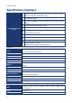
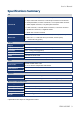
EMX-965GME Specifications Summary 1 2 3 Supports Intel socket P Core 2 Duo / Core Duo / Core 2 Solo / Core Solo mobil CPU with 65nm process technology Intel GME965 Chipset Two 200-pin SODIMMs sockets up to 4GB Dual Channel DDR2 533/667 SDRAM 4 Intel Graphics Media Accelerator X3100 5 DVI, Dual 18/24-bit LVDS Features 6 Realtek ALC888 5.
User’s Manual Specifications Summary I/O 3 x USB connectors support additional 6 USB ports 1 x 20-pin ATX Power connector,1 x IDE 40-pin connector for two devices 2 x COM port header,3 x SATA connectors,1 x Front panel audio connector Internal I/O 1 x Audio amplifier connector,1 x System panel connector 1 x LVDS connector,1 x Inverter Power connector,1 x CPU Fan connector 1 x System Fan connector,1 x Digital IO header 1 x SPDIF Out connector reserved 1 x PS/2 Keyboard,1 x PS/2 Mouse,2 x RS-232,1 x VGA por
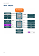
EMX-965GME Block Diagram 10
User’s Manual This chapter describes the main board features and the new technologies it supports.
EMX-965GME Production Introduction 1.1 Before you Proceed Take note of the following precautions before you install motherboard components or change any motherboard settings. z z z z z 12 Unplug the power cord from the wall socket before touching any component.
User’s Manual 1.2 Motherboard Overview Before you install the motherboard, study the configuration of your chassis to ensure that the motherboard fits into it. Refer to the chassis documentation before installing the motherboard. Make sure to unplug the power cord before installing or removing the motherboard. Failure to do so can cause you physical injury and damage motherboard components. 1.2.
EMX-965GME 1.
User’s Manual 1.3.1 Layout Content List Slots Label Function Note Page CF1A Compact Flash connector (Rear side) N/A SO-DIMM1 200-pin SODIMM slot 1 N/A SO-DIMM2 200-pin SODIMM slot 2 N/A PCI1 PCI slot N/A Jumpers Label Function Note Page CCMOS1 Clear CMOS 3 x 1 header, pitch 2.00mm 29 JCOMPWR1,2 COM 1, 2 RI/+5V/+12V selection 3 x 2 header, pitch 2.00mm 30 JCOMPWR3,4 COM 3, 4 RI/+5V/+12V selection 3 x 2 header, pitch 2.00mm 31 3 x 1 header, pitch 2.
EMX-965GME Internal Connector Label Function Note Page AMPJ1 Amplifier connector 4 x 1 header, pitch 2.54mm 35 ATXPWR1 ATX power connector 10 x 2 header 35 COM3 Serial port 3 connector 5 x 2 header, pitch 2.54mm 36 COM4 Serial port 4 connector 5 x 2 header, pitch 2.54mm 36 CPU_FAN1 CPU fan connector 4 x 1 wafer, pitch 2.54mm 37 PWR_FAN1 Power fan connector 3 x 1 wafer, pitch 2.54mm 37 FPIO1 System panel connector 5 x 2 header, pitch 2.
User’s Manual 1.4 Central Processing Unit (CPU) The motherboard comes with a surface mount 478-pin designed for the Intel® socket 479P Core Duo / Core Solo / Core 2 Duo CPU with 65nm process. Take one of the marked corner (with gold triangle) on the CPU. This mark should match a specific corner on the socket to ensure correct installation. z z Make sure the AC power is off before you install the CPU.
EMX-965GME 1.4.1 Installing the CPU 1. Locate the CPU socket on the motherboard. Before installing the CPU, make sure that the socket box is facing towards you. 2. 18 The processor socket comes with a screw to secure the processor, please unlock the screw first.
User’s Manual 3. 4. 5. Position the CPU above the socket and the gold triangular mark on the CPU must align with pin 1 of the CPU socket. Carefully insert the CPU into the socket until it fits in place ‘Gold mark’. Turn the screw to the lock position. The CPU fits in only one correct orientation. DO NOT force the CPU into the socket to prevent bending the connectors on the socket and damaging the CPU. After installation, make sure to plug-in the ATX power cable to the motherboard.
EMX-965GME 1.4.2 Installing the CPU Heatsink and Fan The Intel® socket 479P Core Duo / Core Solo / Core 2 Duo CPU processor requires a specially designed heatsink and fan assembly to ensure optimum thermal condition and performance. z z Install the motherboard to the chassis before you install the CPU fan and heatsink assembly. When you buy a boxed Intel® processor, the package includes the CPU fan and heatsink assembly.
User’s Manual 2. Push down two fasteners at a time in a diagonal sequence to secure the heatsink and fan assembly in place. 3. Connect the CPU fan cable to the connector on the motherboard labelled CPU_FAN1. z z Do not forget to connect the fan cables to the fan connectors. Insufficient air flow inside the system may damage the motherboard components, and hardware monitoring errors can occur if you fail to plug this connector. These are not jumpers! DO NOT place jumper caps on the fan connectors.
EMX-965GME 1.4.3 Uninstalling the CPU Heatsink and Fan 1. Disconnect the CPU fan cable from the connector on the motherboard. 2. Rotate each fastener counterclockwise. 3. Pull up two fasteners at a time in a diagonal sequence to disengage the heatsink and fan assembly from the motherboard 4. Carefully remove the heatsink and fan assembly from the motherboard. Refer to the documentation in the boxed or stand-alone CPU fan package for detailed information on CPU fan installation.
User’s Manual 1.5 System Memory 1.5.1 DIMM Sockets Location The motherboard comes with two 200-pin Double Data Rate 2 (DDR2) SODIMM sockets. A DDR2 module has the same physical dimensions as a DDR DIMM but has a 200-pin footprint compared to the 184-pin DDR DIMM. DDR2 DIMMs are notched differently to prevent installation on a DDR DIMM socket.
EMX-965GME 1.5.2 Memory Configurations You can install 128 MB, 256 MB, 512 MB, 1GB and 2GB DDR2 SDRAM DIMMs into the SODIMM sockets using the memory configurations in this section. z z z z z Installing DDR2 DIMM other than the recommended configurations may cause memory sizing error or system boot failure. Use any of the recommended configurations. Always install DIMMs with the same CAS latency. For optimum compatibility, it is recommended that you obtain memory modules from the same vendor.
User’s Manual 1.5.3 Installing a DDR2 DIMM Make sure to unplug the power supply before adding or removing DIMMs or other system components. Failure to do so may cause severe damage to both the motherboard and the components. 1. 2. 3. 4. Locate the DIMM socket on the board. Hold two edges of the DIMM module carefully, and keep away of touching its connectors. Align the notch key on the module with the rib on the slot. Firmly press the modules into the socket automatically snaps into the mounting notch.
EMX-965GME 1.5.4 Removing a DDR2 DIMM 1. Press the two ejector tabs on the slot outward simultaneously, and then pull out the DIMM module. Support the DIMM lightly with your fingers when pressing the ejector tabs. The DIMM might get damaged when it flips out with extra force.
User’s Manual 1.6 Expansion Slots In the future, you may need to install expansion cards. The following sub‑sections describe the slots and the expansion cards that they support. Make sure to unplug the power cord before adding or removing expansion cards. Failure to do so may cause you physical injury and damage motherboard components. 1.6.1 Installing an Expansion Card 1. Before installing the expansion card, read the documentation that came with it and make the necessary hardware settings for the card.
EMX-965GME 1.6.
User’s Manual 1.7 Jumpers 1.7.1 Clear CMOS (CCMOS1) This jumper allows you to clear the Real Time Clock (RTC) RAM in CMOS. You can clear the CMOS memory of date, time, and system setup parameters by erasing the CMOS RTC RAM data. The onboard button cell battery powers the RAM data in CMOS, which include system setup information such as system passwords. To erase the RTC RAM: 1. Turn OFF the computer and unplug the power cord. 2. Remove the onboard battery. 3.
EMX-965GME 1.7.2 COM1 RI/+5V/+12V Selection (JCOMPWR1, JCOMPWR2) JCOMPWR1 +5V + (Default) 1.7.
User’s Manual 1.7.4 COM3 RI/+5V/+12V Selection (JCOMPWR3, JCOMPWR4) JCOMPWR3 +5V + (Default) 1.7.
EMX-965GME 1.7.
User’s Manual 1.8 Connectors 1.8.1 Rear Panel Connectors No 1 Label KBMS1 Function PS/2 mouse connector 2 3 4,5 DUALCOM1 Serial port connector x 2 VGA_DVI-D1 DVI port USB1, USB2 LAN (RJ-45) connector Description The standard PS/2 mouse DIN connector is for a PS/2 mouse. D-sub 9-pin, male This port allows Gigabit connection to a Local Area Network (LAN) through a network hub. Refer to the table below for the LAN port LED indications.
EMX-965GME No 6 7 8 9,10 Label AUDIO1 Function Line-In port (Light Blue). AUDIO1 Line-Out port (Lime) AUDIO1 USB1, USB2 Microphone port (Pink) USB 2.0 connector 11 VGA_DVI-D1 VGA port 12 KBMS1 34 PS/2 KB connector Description This port connects a tape, CD, DVD player, or other audio sources. This port connects a headphone or a speaker. In 4-channel, 6-channel, and 8-channel configuration, the function of this port becomes Front Speaker Out. This port connects a microphone.
User’s Manual 1.8.2 Amplifier Connector (AMPJ1) 1.8.3 ATX Power Connector (ATXPWR1) This connector is for an ATX Micro-Fit power supply. The plugs from the power supply are designed to fit these connectors in only one orientation. Find the proper orientation and push down firmly until the connectors completely fit. Important notes on the Motherboard Power Requirements z Make sure that your ATX 12V power supply can provide 8A on the +12V lead and at least 1A on the +5-volt standby lead (+5VSB).
EMX-965GME 1.8.4 Serial Port 3 Connector (COM3) 1.8.
User’s Manual 1.8.6 CPU Fan Connector (CPU_FAN1) z z 1.8.7 Do not forget to connect the fan cables to the fan connectors. Insufficient air flow inside the system may damage the motherboard components, and hardware monitoring errors can occur if you fail to plug this connector. These are not jumpers! DO NOT place jumper caps on the fan connectors. Power Fan Connector (PWR_FAN1) z z Do not forget to connect the fan cables to the fan connectors.
EMX-965GME 1.8.8 System Panel Connector (FPIO1) This connector supports several chassis-mounted functions. z System Power LED (2-pin PWRLED) This 2-pin connector is for the system power LED. Connect the chassis power LED cable to this connector. The system power LED lights up when you turn on the system power, and blinks when the system is in sleep mode. z ATX Power Button/Soft-off Button (2-pin PWRSW) This connector is for the system power button.
User’s Manual 1.8.9 1.8.10 Primary IDE Connector (IDE1) z Orient the red markings (usually zigzag) on the IDE cable to Pin 1. z Please DO NOT use IDE1 and SATA2 at the same time. This is an incompatible conflict.
EMX-965GME 1.8.11 LCD Inverter Connector (JBKL1) z Signal Description Signal VR ENBKL 1.8.12 40 Digital I/O Connector (JDIO1) Signal Description Bright adjust. Vadj=0.75V ~ 4.25V (Recommended: 4.
User’s Manual 1.8.13 SPI Connector (JSPI1) 1.8.14 Digital Audio Connector (SPDIF_OUT2) This connector is for an additional Sony/Philips Digital Interface (S/PDIF) port(s). Connect the S/PDIF module cable to this connector, then install the module to a slot opening at the back of the system chassis. The S/PDIF module is purchased separately.
EMX-965GME 1.8.15 Serial SATA Connector [Black] (SATA1, SATA2, SATA3) SATA1 SATA2 SATA1 SATA3 SATA2 z z z 42 SATA3 Install the Windows® 2000 Service Pack 4 or the Windows® XP Service Pack1 before using Serial ATA. When using the connectors in Standard IDE mode, connect the primary (boot) hard disk drive to the SATA1 connector. Please DO NOT use IDE1 and SATA2 at the same time. This is an incompatible conflict.
User’s Manual 1.8.16 USB 2.0 Connector (USB3, USB4, USB5) These connectors are for USB 2.0 ports. Connect the USB/GAME module cable to any of these connectors, then install the module to a slot opening at the back of the system chassis. These USB connectors comply with USB 2.0 specification that supports up to 480 Mbps connection speed. USB3 USB4 USB4 USB5 USB3 USB5 Never connect a 1394 cable to the USB connectors. Doing so will damage the motherboard! The USB module is purchased separately.