
Specifications
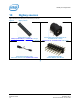
Table Of Contents
- 1 Introduction
- 2 Product Overview
- 3 High-Level Functional Description
- 3.1 Intel® Edison kit for Arduino* header signal list
- 3.2 Intel® Edison kit for Arduino* PWM swizzler
- 3.3 Intel® Edison kit for Arduino* analog inputs
- 3.4 Intel® Edison kit for Arduino* signal pullup resistors
- 3.5 Intel® Edison kit for Arduino* USB interface
- 3.6 Intel® Edison kit for Arduino* power supply
- 3.7 Intel® Edison kit for Arduino* expansion mechanicals
- 4 Powering the Intel® Edison kit for Arduino*
- 5 Batteries
- 6 Layout
- 7 Handling
- 8 Debug UART and Low-Power Sleep Mode
- 9 Buttons
- 10 Digikey sources
- 11 Shield pin configuration

Shield pin configuration
11.6 Configure IO18/IO19 for I
2
C connectivity
To configure IO18 and IO19 for I
2
C connectivity, do the following:
1. Refer to Table 2 for the GPIO numbers. According to Table 2, the GPIO numbers for IO18 and IO19 are 28
and 27, respectively.
2. According to Table 4, GPIO 204 must be set to 1 to select GPIO/I
2
C, and GPIO 28 pin-mux must be set to
‘mode1’ to select I
2
C for IO18.
3. According to Table 4, GPIO 205 must be set to 1 to select GPIO/I2C, and GPIO 27 pin-mux must be set to
‘mode1’ to select I
2
C for IO19.
4. GPIO 14 and GPIO 165 are also connected to the I
2
C signals, and should be configured as high-
impedance inputs when I
2
C is in use on these pins, to prevent them driving a signal on the I
2
C bus.
5. According to Table 7, GPIO 236 must be set to 0 to disable the output direction for GPIO 14, and GPIO 237
must be set to 0 to disable the output direction for GPIO 165.
6. According to Table 7, GPIO 212 and 213 must be set as high-impedance inputs to disable the pullup
resistors for IO18 and IO19, respectively.
7. According to Table 6, the TRI_STATE_ALL signal is controlled by GPIO 214.
After you have gathered all of this information, enter the following commands in Linux:
# echo 28 > /sys/class/gpio/export
# echo 27 > /sys/class/gpio/export
# echo 204 > /sys/class/gpio/export
# echo 205 > /sys/class/gpio/export
# echo 236 > /sys/class/gpio/export
# echo 237 > /sys/class/gpio/export
# echo 14 > /sys/class/gpio/export
# echo 165 > /sys/class/gpio/export
# echo 212 > /sys/class/gpio/export
# echo 213 > /sys/class/gpio/export
# echo 214 > /sys/class/gpio/export
# echo high > /sys/class/gpio/gpio214/direction
# echo high > /sys/class/gpio/gpio204/direction
# echo high > /sys/class/gpio/gpio205/direction
# echo in > /sys/class/gpio/gpio14/direction
# echo in > /sys/class/gpio/gpio165/direction
# echo low > /sys/class/gpio/gpio236/direction
# echo low > /sys/class/gpio/gpio237/direction
# echo in > /sys/class/gpio/gpio212/direction
# echo in > /sys/class/gpio/gpio213/direction
# echo mode1 > /sys/kernel/debug/gpio_debug/gpio28/current_pinmux
# echo mode1 > /sys/kernel/debug/gpio_debug/gpio27/current_pinmux
# echo low > /sys/class/gpio/gpio214/direction
You should be able to use IO18 and IO19 for I
2
C communication.
Intel® Edison Kit for Arduino*
Hardware Guide December 2014
30 Document Number: 331191-004