
Specifications
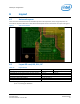
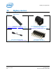
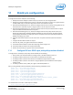
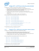
Table Of Contents
- 1 Introduction
- 2 Product Overview
- 3 High-Level Functional Description
- 3.1 Intel® Edison kit for Arduino* header signal list
- 3.2 Intel® Edison kit for Arduino* PWM swizzler
- 3.3 Intel® Edison kit for Arduino* analog inputs
- 3.4 Intel® Edison kit for Arduino* signal pullup resistors
- 3.5 Intel® Edison kit for Arduino* USB interface
- 3.6 Intel® Edison kit for Arduino* power supply
- 3.7 Intel® Edison kit for Arduino* expansion mechanicals
- 4 Powering the Intel® Edison kit for Arduino*
- 5 Batteries
- 6 Layout
- 7 Handling
- 8 Debug UART and Low-Power Sleep Mode
- 9 Buttons
- 10 Digikey sources
- 11 Shield pin configuration

Shield pin configuration
6.3 LEDs
The Intel® Edison kit for Arduino has three LEDs. (See Figure 5 for locations.)
• DS1 is the reset LED. It will turn on when the Intel® Edison processor is running. When the processor is in
reset and asserting RESET_OUT# low, it will turn off.
• DS2 is the standard LED on the Arduino* board. It runs using the ‘blink’ code or whenever Digital I/O 13 is
asserted High. It can be used as an indicator under direct control.
• DS3 is the battery charging LED. It will turn on when the LTC4067 is charging an attached battery.
§
Intel® Edison Kit for Arduino*
Hardware Guide December 2014
22 Document Number: 331191-004