
Specifications
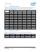
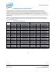
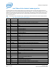
Table Of Contents
- 1 Introduction
- 2 Product Overview
- 3 High-Level Functional Description
- 3.1 Intel® Edison kit for Arduino* header signal list
- 3.2 Intel® Edison kit for Arduino* PWM swizzler
- 3.3 Intel® Edison kit for Arduino* analog inputs
- 3.4 Intel® Edison kit for Arduino* signal pullup resistors
- 3.5 Intel® Edison kit for Arduino* USB interface
- 3.6 Intel® Edison kit for Arduino* power supply
- 3.7 Intel® Edison kit for Arduino* expansion mechanicals
- 4 Powering the Intel® Edison kit for Arduino*
- 5 Batteries
- 6 Layout
- 7 Handling
- 8 Debug UART and Low-Power Sleep Mode
- 9 Buttons
- 10 Digikey sources
- 11 Shield pin configuration

Shield pin configuration
5 Batteries
The rechargers chosen on the Intel® Edison kit for Arduino* and the Intel® Edison Breakout Board were designed for
lithium-ion or lithium-polymer batteries. Follow the manufacturer’s guidelines when charging batteries. Generally,
charging current should not exceed 50 to 70% of the rated capacity. For example, a 200 mAH battery should be
charged with 70% • 200 mA = (140 mA).
The Intel® Edison kit for Arduino* has a 100 mA charging current; the Intel® Edison Breakout Board has a 190 mA
charging current.
§
Intel® Edison Kit for Arduino*
Hardware Guide December 2014
20 Document Number: 331191-004