
Specifications
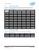
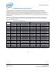
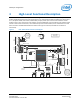
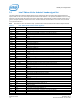
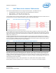
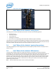
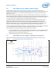
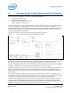
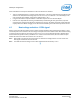
Table Of Contents
- 1 Introduction
- 2 Product Overview
- 3 High-Level Functional Description
- 3.1 Intel® Edison kit for Arduino* header signal list
- 3.2 Intel® Edison kit for Arduino* PWM swizzler
- 3.3 Intel® Edison kit for Arduino* analog inputs
- 3.4 Intel® Edison kit for Arduino* signal pullup resistors
- 3.5 Intel® Edison kit for Arduino* USB interface
- 3.6 Intel® Edison kit for Arduino* power supply
- 3.7 Intel® Edison kit for Arduino* expansion mechanicals
- 4 Powering the Intel® Edison kit for Arduino*
- 5 Batteries
- 6 Layout
- 7 Handling
- 8 Debug UART and Low-Power Sleep Mode
- 9 Buttons
- 10 Digikey sources
- 11 Shield pin configuration
Shield pin configuration
Figure 4 PWM swizzler on the Intel® Edison kit for Arduino*
3.3 Intel® Edison kit for Arduino* analog inputs
The analog inputs are fed to an ADS7951 A/D converter. This device has the following features:
• 20 MHz clock rate
• 12-bit A/D conversion
• 1 MHz sample rate
• 70 dB signal to noise ratio
• 0 to 2.5 V or 0 to 5 V input range (select either AREF or IOREF via jumper J8 onboard)
The analog inputs are multiplexed with digital I/O using SN74LVC2G53 analog switches. These switches isolate the
digital I/O from the analog input to prevent crosstalk. The SN74LVC2G53 also has an inhibit pin that places the I/O
in a tristate condition. The switch also has low on state resistance of 15 ohm at 4.5 V VCC.
3.4 Intel® Edison kit for Arduino* signal pullup resistors
The analog and digital pins can be configured to have an external pull-up resistor connected. The pullup value is
fixed at 47 kohm.
3.5 Intel® Edison kit for Arduino* USB interface
The Intel® Edison compute module has a single USB 2.0 interface. This interface is the primary method for
downloading code. The Intel® Edison compute module is designed to support OTG, using the ID signal. Circuitry on
the Intel® Edison kit for Arduino* board uses a USB multiplexer, and an external switch to configure the USB
interface as a host port or device port. SW1 is a slider switch which selects between host mode and device mode.
When the slider is switched towards the USB standard size Type A connector, the Intel® Edison compute module
will go to host mode. When the switch is towards the micro USB Type B connector, the Intel® Edison compute
module will go to device mode.
Note: USB host mode always requires use of an external power adapter.
Intel® Edison Kit for Arduino*
Hardware Guide December 2014
16 Document Number: 331191-004