
Specifications

Shield pin configuration
2.1 Shield pin GPIO mapping
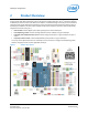
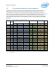
Table 2 describes the mapping of GPIO and PWM pin numbers (in Linux) to shield I/O pins. The following details
are included:
• Shield pin. Digital I/O pin number as per Arduino* Uno* pin numbering scheme.
• GPIO (Linux). The pin number assigned under Linux.
• Muxed functions. Other signals available on this shield pin, as they appear on the schematic.
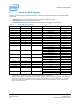
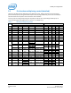
Table 2
Shield pin GPIO mapping
Shield pin GPIO (Linux) PWM (Linux) Muxed functions Notes
IO0
130
UART1_RXD
IO1
131
UART1_TXD
IO2
128 UART1_CTS Note 1.
IO3
12 0 PWM0 Note 2.
IO4
129
UART1_RTS
Note 1.
IO5
13
1
PWM1
Note 2.
IO6
182
2
PWM2
Note 2.
IO7
48
─
IO8
49
─
IO9
183 3 PWM3 Note 2.
IO10
41
??
SPI_2_SS1
I2S_2_FS
Note 1.
PWM4_OUT
Note 2.
IO11
43 ?? SPI_2_TXD
I2S_2_TXD Note 1.
PWM5_OUT Note 2.
IO12
42
SPI_2_RXD
I2S_2_RXD
Note 1.
IO13
40
SPI_2_CLK
I2S_2_CLK Note 1.
IO14
44 AIN0
IO15
45
AIN1
IO16
46
AIN2
IO17
47
AIN3
IO18
14 AIN4
I2C_6_SDA
IO19
165 AIN5
I2C_6_SCL
1 Some additional functions are available on certain SoC pins, such as I2S and UART flow control, but they are not currently
supported by the Arduino library. However, it may be possible to use these from Linux.
2 Depends on PWM swizzler. The SoC offers only four PWM pins. A jumper pin matrix labeled “PWM swizzler” on the baseboard
allows these four pins to be connected to any subset of the six shield-header pins normally used for PWM. From the factory,
IO3, IO5, IO6, and IO9 will be connected to the four available SoC PWM pins as described above. You can manually alter
these to connect IO10 or IO11.
Intel® Edison Kit for Arduino*
Hardware Guide December 2014
8 Document Number: 331191-004