
Specifications
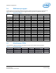
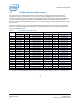
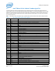
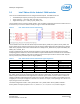

Shield pin configuration
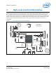
3 High-Level Functional Description
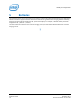
The Intel® Edison kit for Arduino*expansion board is designed to be hardware and software pin-compatible with
Arduino shields designed for the Uno R3. Digital pins 0 to 13 (and the adjacent AREF and GND pins), analog inputs
0 to 5, the power header, ICSP header, and the UART port pins (0 and 1) are all in the same locations as on the
Arduino Uno R3. This is also known as the Arduino 1.0 pinout. Additionally, the Intel® Edison kit for Arduino* board
includes a micro SD card connector, a micro USB device port connected to UART2, and a combination micro USB
device connector and dedicated standard size USB 2.0 host Type-A connector (selectable via a mechanical
microswitch).
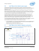
Figure 2 Intel® Edison kit for Arduino* block diagram
3.3V <-> 5V Level
Translation provided
on bo ard be tw een
al l Edison I/O and
Shiel d He ade rs
UAR T 2
Ho st USB
Full size
Type-A
USB 0TG
Client
USB
Micro
Type-B
7 to 15 V Brick
Power Supply
FLA S
H
ADC
SPI0
SPI
1 RX
4 ~IO3
7 ~IO6
5 IO4
6 ~IO5
8 IO7
3 IO2
2 TX
1 IO8
4 ~IO11
7 GND
5 IO12
6 IO13
8 AREF
3 ~IO10
2 ~IO9
9 SDA
10 SCL
VIN 8
5V 5
IOREF 2
3.3V 4
RESET 3
1
GND 6
GND 7
A5 6
A2 3
A1 2
A0 1
A3 4
A4 5
SD
Micro SD
Connector
UART 1
5V
VIN (7 to 15 V)
I2C
3.3V
DIGITAL (P WM~)
ANA LO G I N POWER
GPIO
GPIO
SPI
2
6
6
2
4 ~IO11
6 GND
2 5V
RESET 5
IO13 3
IO12 1
ICS P
IOREF Ju mper
selects 3.3 or 5 V
Shiel d Ope ra ti on
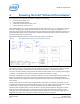
Intel® Edison
FLA S HMUX
Level
Shifter
Level Shifter
Port
Expander
Port
Expander
I2C
DIR
GPIO
6
SEL &PUL L UP
Level Shifter
Level Shifter
FLA S HMUX
2
4
Port
Expander
Port
Expander
DIR &PUL L U P
JUMPE R
SLECTION
3
I2C
3
USB MUX
Client
USB
Micro
Type-B
UART – USB
FTDI
Intel® Edison Kit for Arduino*
December 2014 Hardware Guide
Document Number: 331191-004 13