
Specifications
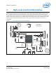
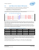

Shield pin configuration
2.4 GPIO interrupt support
All GPIO inputs on the Intel® Edison platform are interrupt-capable, and all interrupt types are supported on all
inputs. Table 5 lists the specific edge- and level-triggered interrupt types that are supported on each pin.
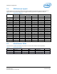
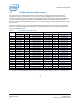
Table 5 GPIO interrupt support
Shield pin GPIO Edge-triggered Level-triggered
1
Linux
Rising
Falling
Both
Low High
IO0
130
Y
Y
Y
Y
Y
IO1
131 Y Y Y Y Y
IO2
128 Y Y Y Y Y
IO3
12
Y
Y
Y
Y
Y
IO4
129
Y
Y
Y
Y
Y
IO5
13
Y
Y
Y
Y
Y
IO6
182 Y Y Y Y Y
IO7
48 Y Y Y Y Y
IO8
49 Y Y Y Y Y
IO9
183
Y
Y
Y
Y
Y
IO10
41
Y
Y
Y
Y
Y
IO11
43 Y Y Y Y Y
IO12
42 Y Y Y Y Y
IO13
40 Y Y Y Y Y
IO14
44
Y
Y
Y
Y
Y
IO15
45
Y
Y
Y
Y
Y
IO16
46
Y
Y
Y
Y
Y
IO17
47 Y Y Y Y Y
IO18
14 Y Y Y Y Y
IO19
165 Y Y Y Y Y
1. Level-triggered interrupts are not supported by the Arduino* library, a limitation of the GPIO sysfs interface.
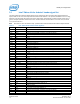
2.5 Miscellaneous GPIOs
The GPIOs listed in Table 6 are used for other platform functions and for Arduino shield compatibility.
Table 6
Miscellaneous GPIOs
Function GPIO pin GPIO Linux Direction Power-on default
1
Initial setup
TRI_STATE_ALL
U17_IO1.6
214
Output
Pulled up input*
SHLD_RESET
U17_IO1.7
215
Output
Pulled up input*
SHLD_RESET
U17_IO0.7 207 Input Pulled up input*
1 These pins are pulled up inputs at power-on. In this state, they have the same effect as outputs set high.
Intel® Edison Kit for Arduino*
December 2014 Hardware Guide
Document Number: 331191-004 11