
Laptop User Manual

Dual-Core Intel Xeon processor LV / E7520 Chipset / 6300ESB ICH
Dual-Core Intel
®
Xeon
®
processor LV with Intel
®
E7520 Chipset and Intel
®
6300ESB ICH
User’s Manual April 2007
50 Order Number: 311274-009
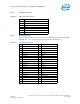
6.3.3 Floppy Drive Connector
The evaluation board provides one 34-pin floppy connector, which is located at J1K1.
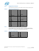
6.3.4 Front Panel Connector
The development kit is not shipped with a chassis, so the front panel connector is
unused by default. However, if you want to place your evaluation board in a chassis,
refer to Table 15 for the pinout of the front panel connector J2G1.
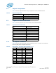
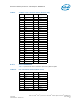
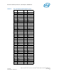
Table 14. Floppy Drive Connector Pinout
Pin Signal Pin Signal
1GND 18DIR#
2Drive Enable 0 19GND
3GND 20STEP#
4Reserved 21GND
5Key 22Write Data#
6Drive Enable 1 23GND
7GND 24Write Gate#
8Index 25GND
9 GND 26 Track 00#
10 Motor Enable A# 27 GND
11 GND 28 Write Protect#
12 Reserved 29 GND
13 GND 30 Read Data#
14 Drive Select 0# 31 GND
15 GND 32 Side 1 Select#
16 Reserved 33 GND
17 GND 34 Diskette Change#
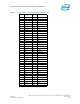
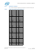
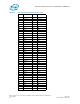
Table 15. Front Panel Connector Pinout
Pin Connector Description Pin Connector Description
1V
CC
2 HD_ACT_LED_N
3V
CC
4FPNTPNL_PWR_LED
5 GND 6 FP_PWR_BTN_N
7 FP_RST_BTN_N 8 GND
9 GND 10 No Pin