
Datasheet


Datasheet 57
MCH Register Description
4.2 Configuration Process and Registers
4.2.1 Platform Configuration Structure
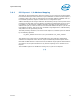
The DMI physically connects the MCH and the Intel ICH9; thus, from a configuration
standpoint, the DMI is logically PCI bus 0. As a result, all devices internal to the MCH
and the ICH appear to be on PCI bus 0.
Note: The ICH9 internal LAN controller does not appear on bus 0 – it appears on the external
PCI bus and this number is configurable.
The system’s primary PCI expansion bus is physically attached to the ICH and from a
configuration perspective, appears to be a hierarchical PCI bus behind a PCI-to-PCI
bridge; therefore, it has a programmable PCI Bus number. The PCI Express interface
appears to system software to be a real PCI bus behind a PCI-to-PCI bridge that is a
device resident on PCI bus 0.
Note: A physical PCI bus 0 does not exist; DMI and the internal devices in the MCH and ICH
logically constitute PCI Bus 0 to configuration software (see Figure 8).
Figure 8. Conceptual Platform PCI Configuration Diagram
CPU
PCI Configuration Window
in I/O Space
Manageability
Engine Device
Bus 0
Device 3
Bus 0
Direct Media Interface
DRAM Controller
Interface Device
Bus 0
Device 0
MCH
Secondary Host-
PCI Express Bridge
Bus 0 Device 6
Primary Host-PCI
Express Bridge
Bus 0 Device 1